 |
|||
|
|
|||
|
Page Title:
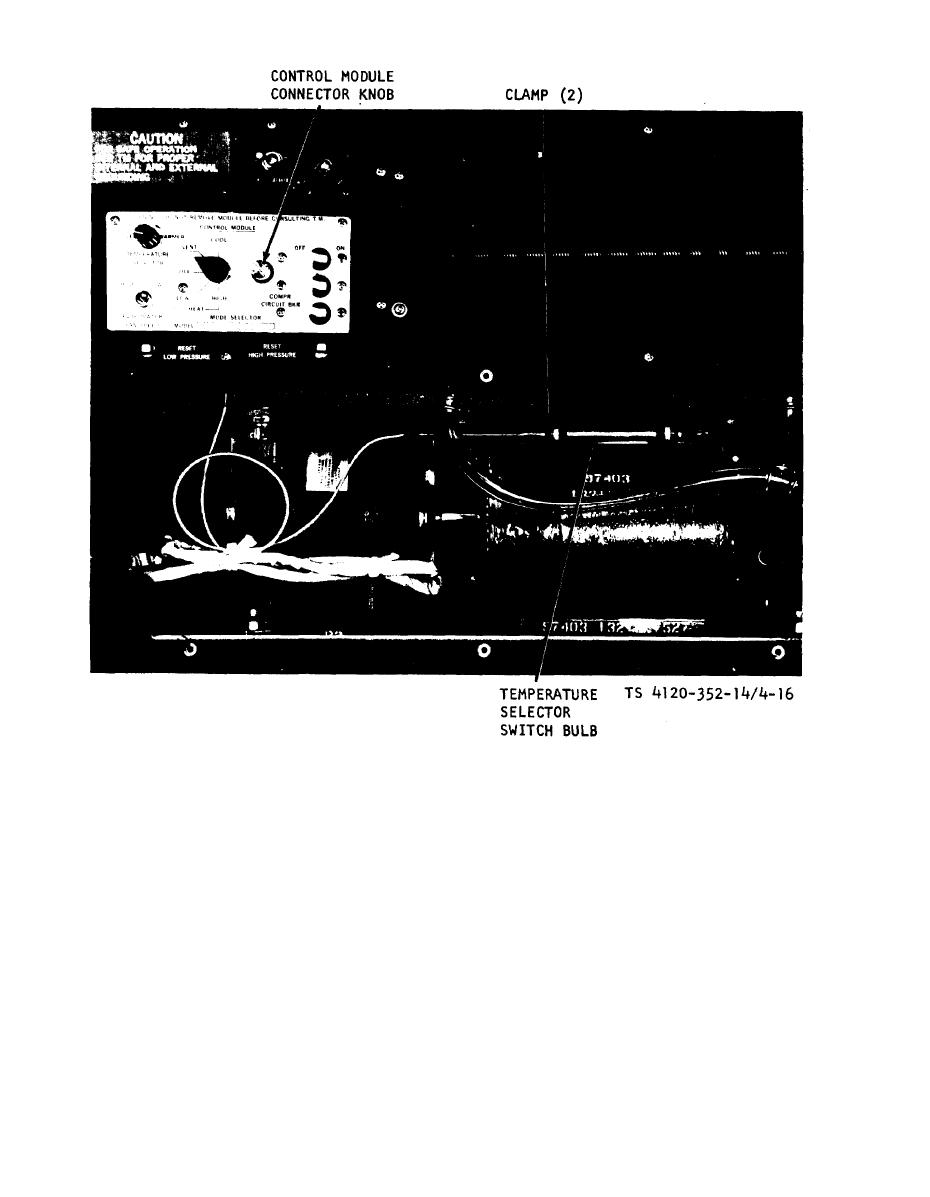
Figure 4-16. Control module connector knob and bulk mounting. |
|
||
| ||||||||||
|
|
 TM 5-4120-352-14
Figure 4-16. Control module connector knob and bulk mounting.
(4) Temperature Selector Switch. Check
b. Testing.
(1) General. Remove four screws securing
for continuity between common terminal 1 and blue
cover to frame. Remove capillary tube grommet and
terminal 2. Switch should close when temperature
slide cover from module. Pull capillary tube bulb
drops below setting. Turn switch knob to full
through hole in cover. To test individual com-
COOLER position. Switch should be open. Turn
ponents, mark and disconnect leads, and check for
switch knob toward WARMER. Switch should close
,continuity. Refer to schematic diagram as a guide
as setting becomes higher than bulb temperature.
and refer to the following additional instructions.
Replace defective switch.
(2) Circuit Breaker. Check for continuity
(5) Mode Selector Rotary Switch. Refer to
between corresponding terminals in closed position.
wiring diagram chart showing connections made by
Check for proper functioning in open position. Re-
switch in various switch positions. Check for con-
place defective circuit breaker.
tinuity. Replace defective switch.
(3) Evaporator Fan Toggle Switch. Check
c. Disassembly.
for continuity in both positions. Replace defective
(1) General. Disassembly is limited to re-
switch.
4-34
|
|
Privacy Statement - Press Release - Copyright Information. - Contact Us |
