 |
|||
|
|
|||
|
Page Title:
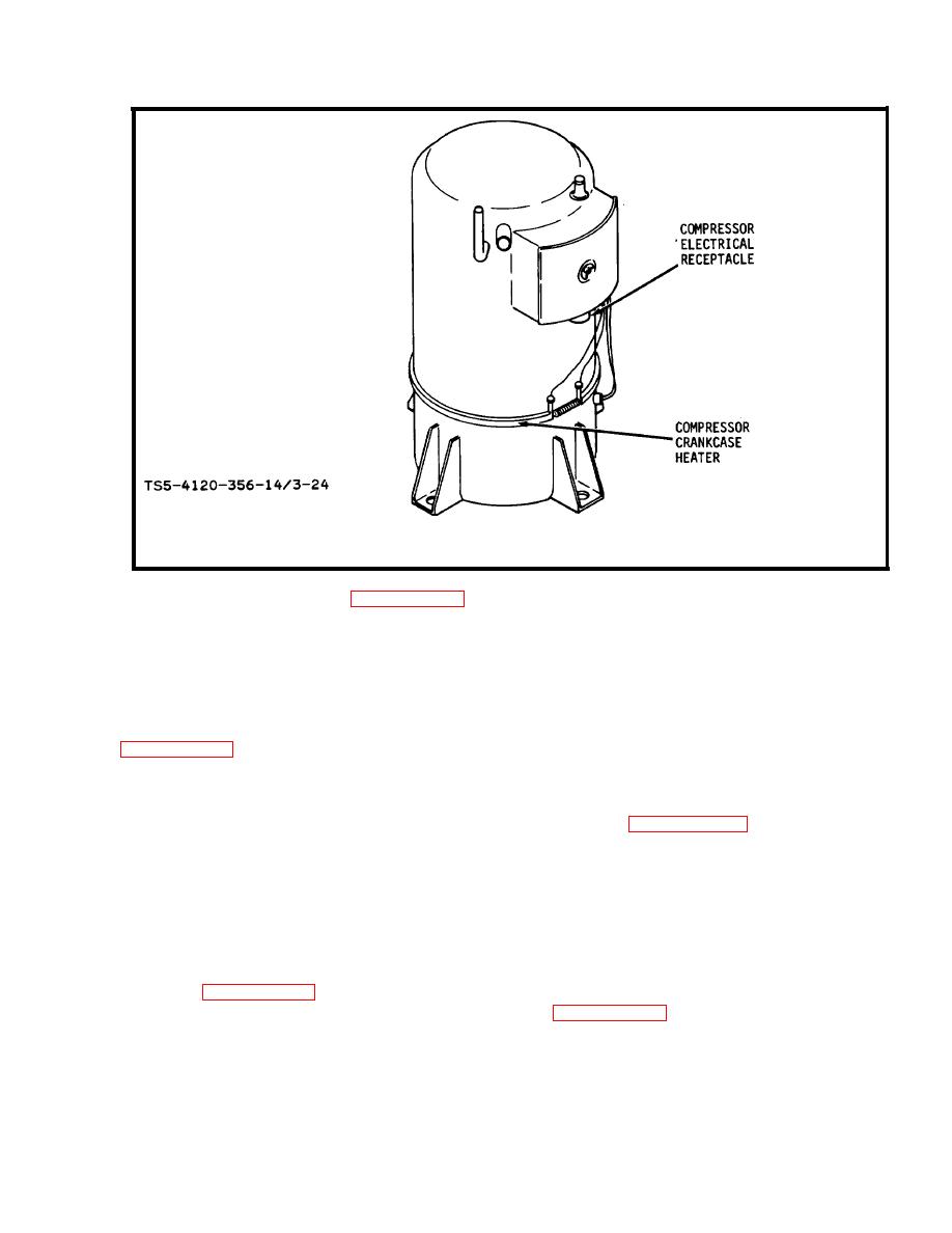
Figure 3-24. Location of compressor crankcase heater |
|
||
| ||||||||||
|
|
 TM 5-4120-356-14
Figure 3-24. Location of compressor crankcase heater
(4) Refer to figure 3-25 and test the liquid line Solenoid valve L1 and
the pressure equalizer solenoid valve L2.
(5) If both solenoid valves test OK, proceed to step (8).
(6) In case of test failure of solenoid valve L1, proceed as follows:
( a ) Disconnect plug P5 f ran liquid line solenoid valve L1. (See
(b) Check for continuity across pins A and B of receptacle J5 on
solenoid valve L1.
(c) If an open circuit is found, see figure 3-26 and replace the
solenoid valve coil.
(d) If no open circuit is found, check for continuity between pin
A of plug P5 and pin K of plug P3, and between pin B of plug P5 and pin H of plug P3.
(e)
Replace
electrical
tiring
if
any
open
circuit
is
found.
(f) After replacement of solenoid valve coil or electrical wiring,
refer to figure 3-25 and connect plug P5 to receptacle J5 on liquid line solenoid
valve L1, then repeat test procedure given in figure 3-25 for liquid line solenoid
valve L1.
(g) If repeat test of liquid line solenoid valve is satisfactory,
proceed to step (8).
|
|
Privacy Statement - Press Release - Copyright Information. - Contact Us |
