 |
|||
|
|
|||
|
Page Title:
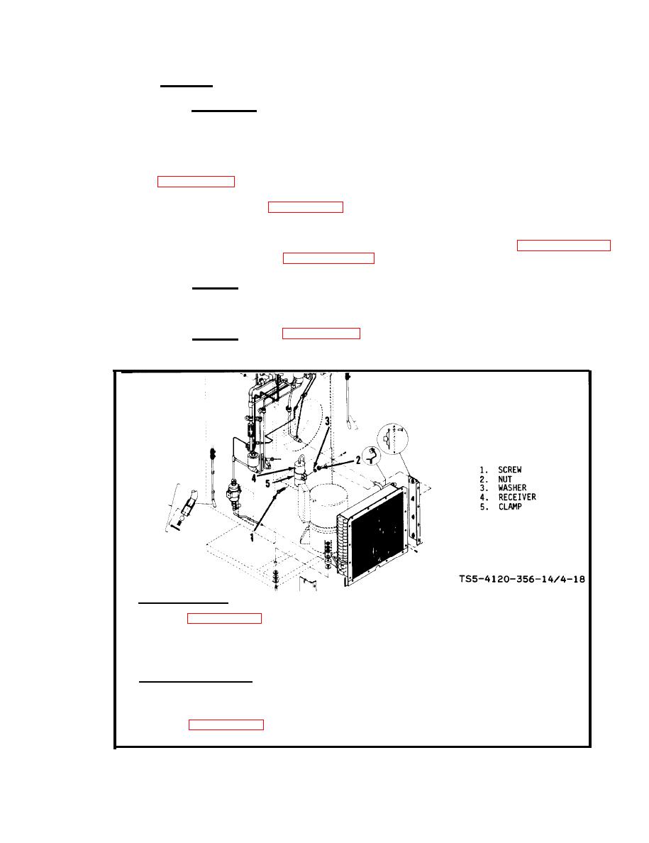
Figure 4-18. Removal and installation of receiver |
|
||
| ||||||||||
|
|
 TM 5-4120-356-14
i.
Receiver.
( 1 ) I n s p e ct i o n .
(a) Turn the selector switch to the "OFF" position and disconnect
the air conditioner from the electrical power source.
(b) Partially remove the junction box to provide access to the re-
ceiver (see figure 3-12).
(c) Refer to figure 4-18 and inspect the receiver for damage which
would impair serviceability.
(d) Check the receiver for leaks in accordance with paragraph 4-4c.
I f any leaks are found, refer to paragraph 4-4d and make repairs.
( 2 ) R e p l a c e . R e p l a c e the receiver if evidence is found of damage which
w o u l d impair serviceability, or if unrepairable leaks are found. Refer to steps (3)
and (4) for removal of defective receiver and the installation of a new receiver.
(3) Removal. (See figure 4-18.)
REMOVAL OF RECEIVER
1. REFER TO PARAGRAPH 4-14i FOR PRELIMINARY STEPS IN MAINTENANCE OF RECEIVER.
2. DISCONNECT TUBING FROM RECEIVER (4).
3. REMOVE SCREW (1), NUT (2) AND WASHER (3) FROM CLAMP (5).
4. REMOVE RECEIVER (4) FROM CLAMP (5) AND FROM UNIT.
INSTALLATION OF RECEIVER
1. POSITION RECEIVER (4) IN CLAMP (5) AND SECURE WITH SCREW (1), WASHER (3) AND NUT (2).
2. CONNECT TUBING TO RECEIVER (4).
3. REFER TO PARAGRAPH 4-14i FOR FINAL STEPS IN MAINTENANCE OF RECEIVER.
|
|
Privacy Statement - Press Release - Copyright Information. - Contact Us |
