 |
|||
|
|
|||
|
Page Title:
Table 4-1. TROUBLESHOOTING (cont.) |
|
||
| ||||||||||
|
|
 TM 5-4120-359-14
TM 5-21
Table 4-1. TROUBLESHOOTING (cont.)
MALFUNCTION
TEST OR INSPECTION
CORRECTIVE ACTION
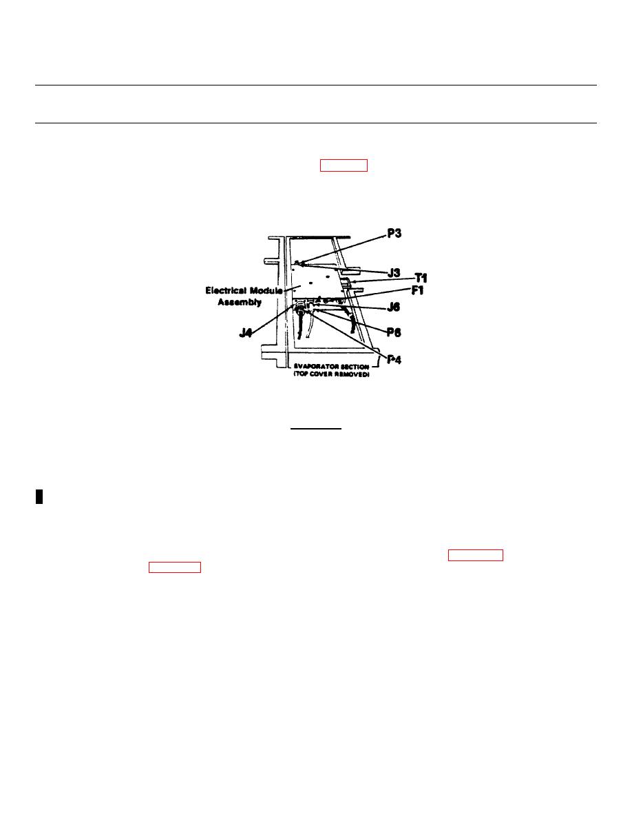
Step 10.
Check electrical fuse F1.
(a) Remove power
(b) Remove top cover, evaporator. (See para 3-21.)
(c) Remove fuse from fuseholder (on left side of electrical module assembly).
(d) Examine fuse and test for continuity.
Replace if bad.
Step 11.
Check transformer T1 output.
WARNING
The following test must be conducted with the power on.
Exercise extreme
caution.
(a)
Apply power.
(b)
Measure ac voltage between T1-7 and T1-8.
(c)
If 27 to 33 Vac is indicated, go to step 12.
(d)
If not, check transformer input.
(e)
If 197 to 229 Vac is indicated,
Replace transformer
(f) If 197 to 229 Vac is not indicated, use electrical schematic (figure 4-2) or wiring diagram
Repair or replace defects as indicated.
Step 12.
Check rectifier CR1 and wiring harness.
(a) Disconnect P4 from J4 (left side of electrical module assembly).
4-6 Change 3
|
|
Privacy Statement - Press Release - Copyright Information. - Contact Us |
|
|
Integrated Publishing, Inc. - A (SDVOSB) Service Disabled Veteran Owned Small Business
|

