 |
|||
|
|
|||
|
Page Title:
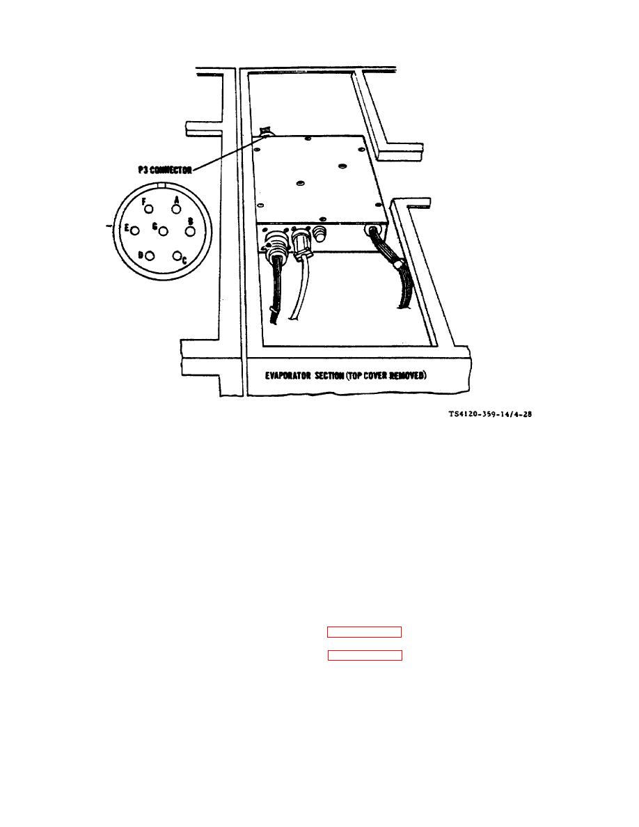
Figure 4-28. Heater Test (Installed) |
|
||
| ||||||||||
|
|
 TM 5-4120-359-14
Figure 4-28. Heater Test (Installed)
(2) Using multimeter, measure resistance between pins in P3 connector: (Pin G is not used.)
A to C, Resistance should be 13 to 19 ohms.
A to B, Resistance should be 13 to 19 ohms.
B to C, Resistance should be 13 to 19 ohms.
D to E, Resistance should be 20 to 26 ohms.
D to F, Resistance should be 20 to 26 ohms.
E to F, Resistance should be 20 to 26 ohms.
(3) If any of the above tests show a failure proceed to paragraph 4-32.
Follow-on Procedures: 1. Install top evaporator cover. (See paragraph 3-21.)
2. Connect power.
4-73
|
|
Privacy Statement - Press Release - Copyright Information. - Contact Us |
|
|
Integrated Publishing, Inc. - A (SDVOSB) Service Disabled Veteran Owned Small Business
|

