 |
|||
|
|
|||
|
Page Title:
TEMPERATURE CONTROL COMPONENT BOARD (A1) TEST |
|
||
| ||||||||||
|
|
 TM 5-4120-359-14
b. Installation
(1) Position transformer (T1) on module housing. Using screwdriver and wrench, install four each screws, flat
washers, lockwashers, and nuts.
(2) Using knife, cut six pieces of heat shrinkable tubing, each one-half inch (1.27 cm) long and slide onto wires
and varistor.
(3) Using soldering gun, solder leads to transformer terminals according to wire markings, tags, and wiring
diagram figure 4-3. Solder varistor (RV4) to terminals 7 and 8. Remove tags.
(4) Slip piece of tubing over each transformer terminal and using heat gun, shrink tubing in place.
(5) Place over on box and line up holes.
(6) Using screwdriver, attach the cover with six screws and lockwashers.
Do not overtighten, it will cause
distortion.
Follow-on Procedure: Install evaporator section electrical module assembly. (See paragraph 4-41.)
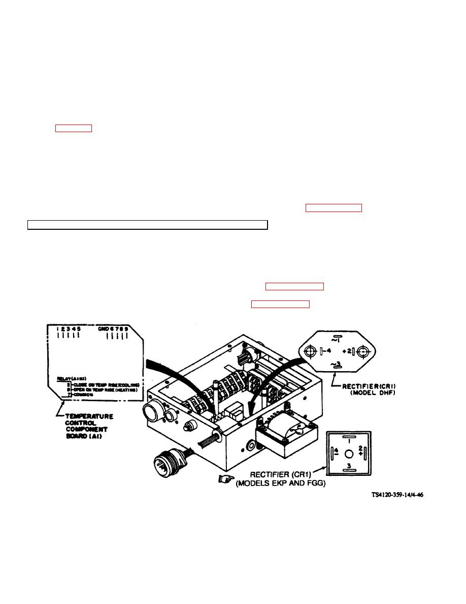
4-47. TEMPERATURE CONTROL COMPONENT BOARD (A1) TEST
Conditions test:
1. Evaporator section electrical module assembly must be connected to an operable air conditioner
and remote control assembly.
2. 208V, 3 phase, 400 Hz power, and power cable must be available.
3. Top evaporator cover must be removed. (See paragraph 3-21.)
4. Top module cover must be removed. (See paragraph 4-42.)
Figure 4-46. Temperature Control Component Board (A1) Test
Change 5 4-103
|
|
Privacy Statement - Press Release - Copyright Information. - Contact Us |
|
|
Integrated Publishing, Inc. - A (SDVOSB) Service Disabled Veteran Owned Small Business
|

