 |
|||
|
|
|||
|
Page Title:
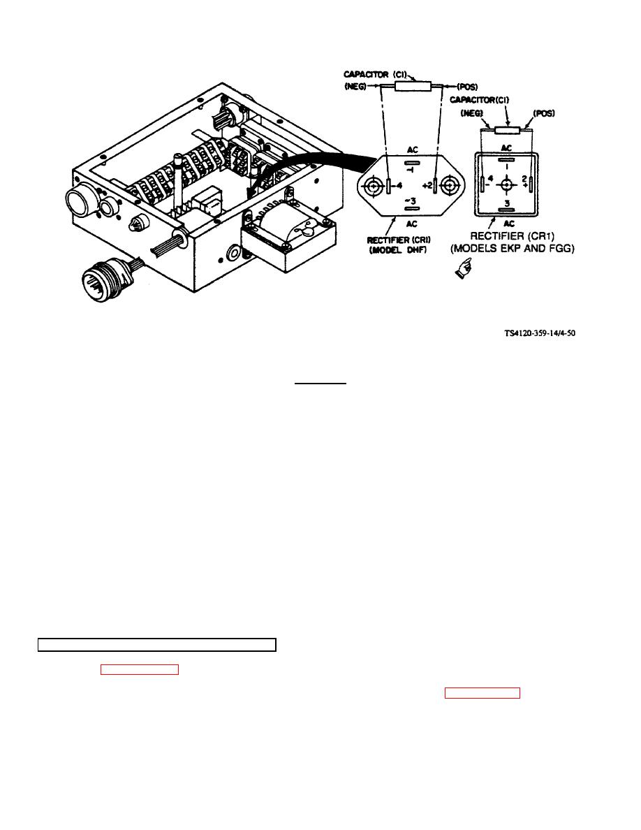
Figure 4-50. Rectifier (CR1) and Capacitor (C1) Test |
|
||
| ||||||||||
|
|
 TM 5-4120-359-14
Figure 4-50. Rectifier (CR1) and Capacitor (C1) Test
WARNING
The following test must be conducted with the power on.
Exercise extreme
caution.
a. Connect power to air conditioner.
b. Turn mode selector switch to LOW HEAT.
c.
Turn temperature control to maximum COOLER.
d. Using multimeter, check voltage across AC terminals of CR1.
Voltage should be 27 to 33 Vac.
e. Using multimeter, check voltage across + and - terminals of CR1. Voltage should be 25 to 31 Vdc. If voltage is
low or there is no voltage, rectifier should be changed.
f.
Remove power to air conditioner.
g. Check capacitor for evidence of overheating. Replace if discolored or damaged.
4-51. RECTIFIER (CR1) AND CAPACITOR (CR1)
For tests, see paragraph 4-50.
Preliminary Procedures: Remove evaporator section electrical module assembly. (See paragraph 4-41.)
Change 5 4-109
|
|
Privacy Statement - Press Release - Copyright Information. - Contact Us |
|
|
Integrated Publishing, Inc. - A (SDVOSB) Service Disabled Veteran Owned Small Business
|

