 |
|||
|
|
|||
|
Page Title:
CAP AND CHAIN AND INSPECTION OF SERVICE VALVES |
|
||
| ||||||||||
|
|
 TM 5-4120-359-14
(6) Use two wrenches. Use one wrench to hold the tubing adapter and the other to tighten the half coupling body
to: suction line (lager) 35-45 foot pounds (48-61 newton meters), discharge line (smaller) 15-20 foot pounds (20-27
newton meters).
(7) Slip the gasket seal over the threaded body end and place body threaded end through the bracket.
(8) Using wrench, tighten jam nut.
(9) Using wrench, carefully reconnect the suction and discharge condenser to evaporator refrigerant metal hose
line connectors to the coupling halves.
(10) Replace the dehydrator. (See paragraph 4-73.)
(11) Leak test the coupling halves, the dehydrator and joints in the repair area in accordance with paragraph 4-8.
(12) Evacuate and charge the refrigerant system in accordance with paragraphs 4-9 and 4-10.
Follow-on Procedures: 1. Install front condenser cover. (See paragraph 3-23.)
2. Connect evaporator and condenser section assemblies. (See paragraph 4-14.)
3. Install air conditioner on shelter. (See paragraph 3-6.)
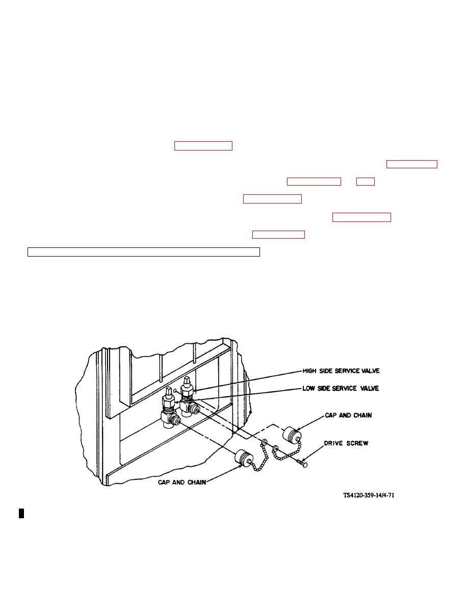
4-67. CAP AND CHAIN AND INSPECTION OF SERVICE VALVES
a. Inspect
(1) Examine LOW SIDE and HIGH SIDE service valves and caps for clean threads.
(2) If dirty, male flare connections and threads should be cleaned. Protective caps should be screwed on.
(3) Missing caps or caps with broken or missing chains, should be replaced.
Figure 4-71. Service Valves and Caps and Chains - Model DHF
4-144 Change 2
|
|
Privacy Statement - Press Release - Copyright Information. - Contact Us |
|
|
Integrated Publishing, Inc. - A (SDVOSB) Service Disabled Veteran Owned Small Business
|

