 |
|||
|
|
|||
|
Page Title:
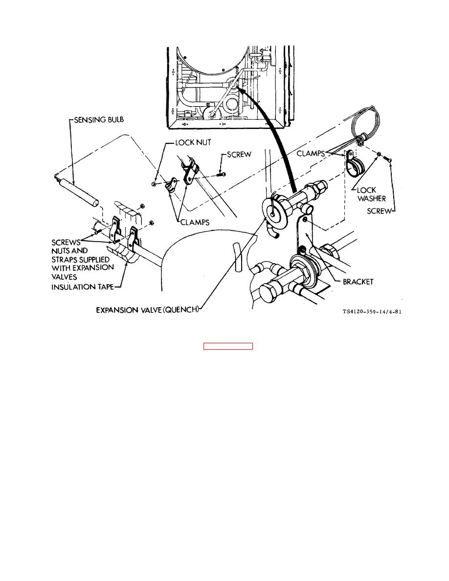
Figure 4-81. Expansion Valve (Quench) |
|
||
| ||||||||||
|
|
 TM 5-4120-359-14
Figure 4-81. Expansion Valve (Quench)
(3) If a leak is suspected or indicated, test per paragraph 4-8.
b. Adjustment
(1) The liquid quench expansion valve is factory set at a superheat of 35 1/2F (1.6 0.3C) at a 32F (0C)
bath temperature.
(2) Due to possible compressor damage, field adjustment of installed quench valve is not recommended.
c.
Removal
(1) Remove insulation from compressor inlet tube to expose sensing bulb and straps.
(2) Using screwdriver and wrench, loosen two screws, nuts, and straps that retain sensing bulb.
(3) Slip the bulb from straps.
(4) Using screwdriver and wrench, remove the screw, lock nut and clamp holding sensing bulb capillary tube to
refrigeration piping.
4-161
|
|
Privacy Statement - Press Release - Copyright Information. - Contact Us |
|
|
Integrated Publishing, Inc. - A (SDVOSB) Service Disabled Veteran Owned Small Business
|

