 |
|||
|
|
|||
|
Page Title:
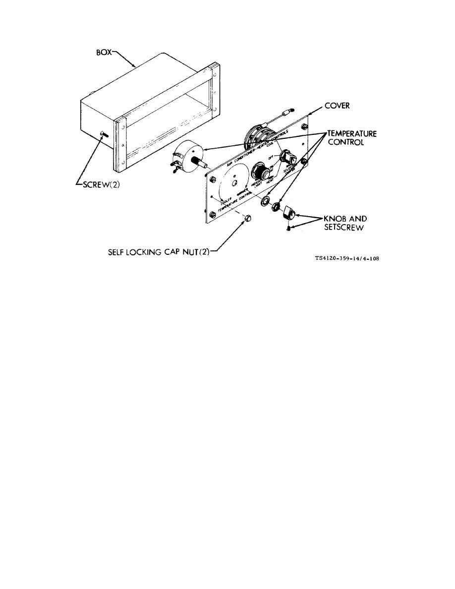
Figure 4-108. Temperature Control |
|
||
| ||||||||||
|
|
 TM 5-4120-359-14
Figure 4-108. Temperature Control
(4) Check that leads are connected, terminals are not bent or broken, and for evidence of overheating. Replace
temperature control if damaged.
(5) Using multimeter, check wire leads and temperature control for continuity shorts and opens.
Temperature control (AR1) CW terminal to CCW terminal internal resistance across pins L and J is
approximately 1,000 ohms.
Temperature control (A1R1) COM terminal to CW terminal internal resistance across pins K and L varies
from 0 to 1,000 ohms at turn of shaft.
b. Removal
(1) Using allen wrench, loosen setscrews in knob.
(2) Remove knob.
(3) Tag and unsolder leads.
(4) Using wrench, remove nut and lock washer from temperature control.
(5) Remove temperature control.
c.
Installation
(1) Place temperature control shaft and positioning tab through holes in cover.
(2) Using wrench, secure temperature control with lock washers and nut.
4-213
|
|
Privacy Statement - Press Release - Copyright Information. - Contact Us |
|
|
Integrated Publishing, Inc. - A (SDVOSB) Service Disabled Veteran Owned Small Business
|

