|
| |
TM 5-4120-361-14
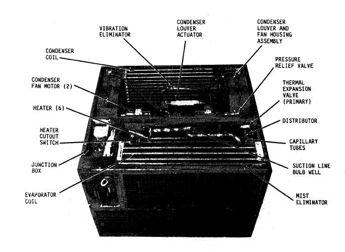
Figure 1-3.
Air conditioner top view, top covers removed
hoses, electrical control panel and con-
trols, main input power connector, con-
trol mdule, and the ventilation air
damper door and control knob. The evap-
orator fan draws air into the unit, from
the space being conditioned, through the
inlet louver and air conditioning fil-
ter, or when required, from the outside
of the unit, through the fresh air fil-
ter and ventilation duct; air is then
forced over the heater elements through
evaporator coil, mist eliminator and
outlet louver.
The outlet louver has
adjustable blades for directing the air
flow into a desired pattern within the
space being conditioned.
The evaporator
fan speed is controlled by a toggle
switch on the control module.
b.
Condenser Section.
The condenser
section
(fig.
1-3) located in the rear
part of the air conditioner contains the
condenser coil, condenser coil guard,
two condenser motors and fans, motor
compressor, condenser fan housings and
louvers, louver actuator, ventilation
air duct, fresh air filter and vent
screen, thermal switch, refrigerant
liquid sight indicator, solenoid valves,
expansion quench valve, discharge bypass
regulation valve, pressure relief valve,
system access service valves, filter-
drier, refrigerant liquid receiver, ac-
cumulator, associated electrical wiring
and refrigerant tubing and an alternate
power input connector.
The condenser
fan speed is controlled by a thermal
switch located on rear of unit.
At am-
bient temperatures of 100°F +5°F (38°C
+3°C) or higher, the condenser fan
motors will operate at high speed (3750
RPM); and at ambient temperatures below
100°F (38°C), the motor will operate at
1-3
|