 |
|||
|
|
|||
|
Page Title:
Figure 3-15. Electrical contactor |
|
||
| ||||||||||
|
|
 TM 5-4120-364-13
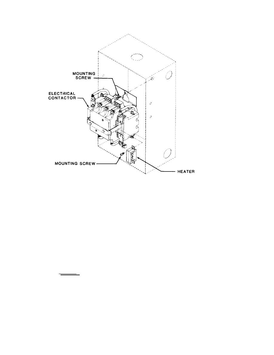
Figure 3-15. Electrical contactor
TS5-4120-364-13/3-15
( b ) Replace defective heaters by removing heater mounting screws on
each side of contactor, then remove heaters.
( c ) Install new or replace heaters and secure with heater mounting
screws.
NOTE
T h e contactor contains two heaters.
Both heaters must be of the same
electrical characteristics. Make sure
that the heaters used are correct for
t h e primary power source being used,
either 120 or 208 volts.
(4) R e p l a c e .
( a ) Position the electrical contractor in the box and secure with
t h r e e mounting screws.
( b ) Refer to figure 3-2 and reconnect electrical leads. Be certain
to connect the electrical leads correctly for the primary power surece being used,
either 120 or 208 volts.
3-30
|
|
Privacy Statement - Press Release - Copyright Information. - Contact Us |
