|
| |
TM5-4120-375-14
COMPRESSOR (CONT.)
LOCATION/ITEM
ACTION
REMARKS
INSPECTION
4. Compressor
a. Inspect for damage.
b.
Repair or replace if damaged.
TEST
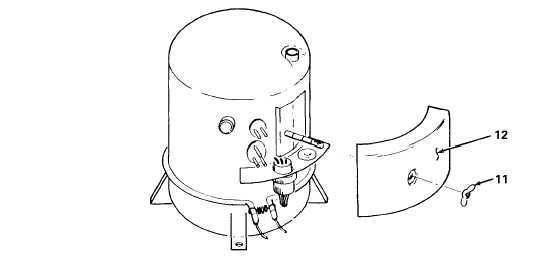
5. Compressor
a. Disconnect plug (P1), from the electrical junction
box on the compressor.
b.
Remove wing nut (11) securing compressor
junction box cover (12) to compressor.
c.
Remove compressor junction box cover.
CAUTION
Schematic is not correct red, white and black wires are yellow wires
striped with red, white and black respectively.
d.
Using a multimeter check for continuity.
1.
COMPRESSOR MOTOR
Test compressor receptacle pins A-B, A-C,
B-C, and D-E. Continuity should be
indicated.
Test points A, B and C to
compressor casing or common ground. No
continuity should be indicated.
Replace
compressor that does not meet continuity
requirements.
5-86
|