Order this information in Print

Order this information on CD-ROM

Download in PDF Format


Click here to make tpub.com your Home Page

Page Title: Removal
Back | Up | Next

Click here for a printable version

Google


Web
www.tpub.com

Home


Information Categories
.... Administration
Advancement
Aerographer
Automotive
Aviation
Combat
Construction
Diving
Draftsman
Engineering
Electronics
Food and Cooking
Math
Medical
Music
Nuclear Fundamentals
Photography
Religion
USMC
   
Products
  Educational CD-ROM's
Printed Manuals
Downloadable Books


TM5-4120-376-14 4-20.  COMPRESSOR,  ACCUMULATOR,  AND  RELATED  PARTS/Inspect,  Test  (Cont) LOCATION/ITEM Removal: 3.  Remove  condenser  fans  and  support  assemblies  in  accordance  with  paragraph  4-15,  page 4-39. Inspection: 1.   Inspect   for   damage. 2.   If   damaged   notify   Direct Test: 1. 2. 3. Compressor   schematic wires   striped   with   red, Support   Maintenance. CAUTION is  deceptive.  Red,  white  and  black  wires  are  yellow white   and   black   respectively. 
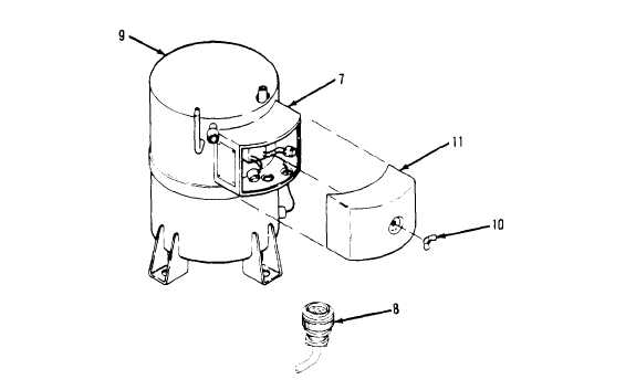
Disconnect  plug  P-7  (8),  from  the  electrical  junction  box  (7)  on  the  compressor  (9). Remove  wing  nut  (10)  securing  compressor  junction  box  cover  (11)  to  compressor. Remove   compressor  junction  box  cover  (11). 4-82

Privacy Statement - Press Release - Copyright Information. - Contact Us - Support Integrated Publishing

Integrated Publishing, Inc. - A (SDVOSB) Service Disabled Veteran Owned Small Business