|
| |
TM5-4120-376-14
4-24. HEATER, TRANSFORMER, RECTIFIER AND RELATED PARTS/Inspect, Test, Replace
(Cont)
LOCATION/ITEM
Removal:
2. Remove ten screws (4) and ten lock washers (5) securing front louver (evaporator inlet) (6)
to housing.
3. Remove two screws (7) two lock washers (8) and two clamps (9) and temperature selector
sensor bulb (10) from left evaporator fan housing assembly (11).
4. Loosen connector knob (12) securing control module (13) to junction box (14).
5. Remove control module and thermostat sensor bulb from evaporator fan housing assembly.
6. Remove junction box in accordance with paragraph 4-22, page 4-107.
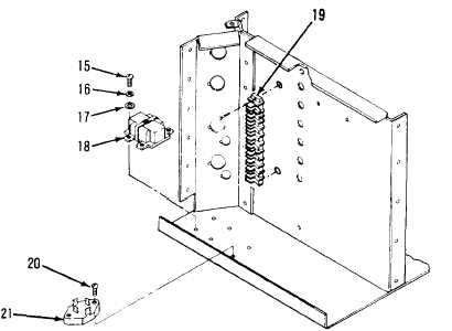
Rectifier/Transformer
1. Remove four screws (15) four lock washers (16) and four flat washers (17) securing
transformer (18) to housing.
2. Tag and remove transformer
wires from terminal board (19).
3. Remove two screws (20)
securing rectifier (21) to
housing.
4. Tag and remove rectifier/
wires from terminal board.
5. Remove transformer and
rectifier assembly.
6. Tag and unsolder the leads
at the transformer.
7. Remove rectifier.
4-147
|