Order this information in Print

Order this information on CD-ROM

Download in PDF Format


Click here to make tpub.com your Home Page

Page Title: Installation
Back | Up | Next

Click here for a printable version

Google


Web
www.tpub.com

Home


Information Categories
.... Administration
Advancement
Aerographer
Automotive
Aviation
Combat
Construction
Diving
Draftsman
Engineering
Electronics
Food and Cooking
Math
Medical
Music
Nuclear Fundamentals
Photography
Religion
USMC
   
Products
  Educational CD-ROM's
Printed Manuals
Downloadable Books


TM5-4120-376-14 5-19.  REFRIGERANT  VALVES  AND  RELATED  TUBING/Test,  Repair,  Replace  (Cont) LOCATION/ITEM Installation: 22.  Install  one  clamp  (13)  around  cap  line  (15)  align  with  hole  in  bulkhead  and  secure  one screw  (12)  one  washer  (14)  and  one  spacer  (20). 23.  Insert  approximately  one  ounce  of  thermal  mastic  (Table  D-1,  Item  20)  in  bulb  well. 24.   Move   expansion   valve   sensor   bulb   (11)   back   and   forth   to   distribute   mastic   (Table   D-1, Item   20)   equally. 25.  Set  bulb  (11)  one  inch  beyond  open  end. 26.  Test,  evacuate  and  charge  in  accordance  with  paragraphs  5-8  through  5-14,  pages  5-10 through  5-19. EXPANSION   VALVE   (THERMAL/QUENCH   VALVE/SOLENOID   VALVE/PRESSURE REGULATING   VALVE 
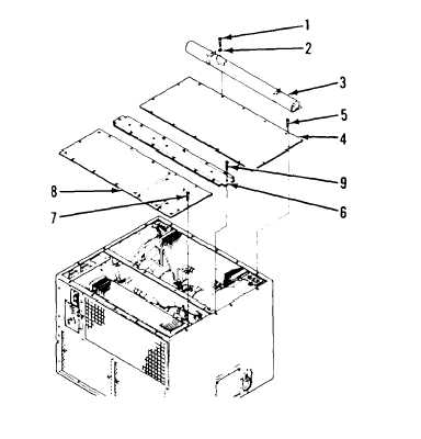
27.   Align   center   cover   (6)   with   holes   in   housing   and   secure   center   cover   to   housing   with seven  screws  (9). 5-44

Privacy Statement - Press Release - Copyright Information. - Contact Us - Support Integrated Publishing

Integrated Publishing, Inc. - A (SDVOSB) Service Disabled Veteran Owned Small Business