|
| |
TM 5-4120-377-14
(6)
(7)
(8)
(9)
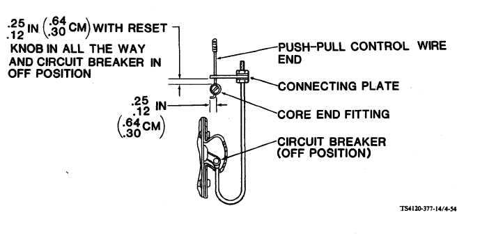
Figure 4-54.
Reset Control Wire Connection
Insert push-pull control wire end through hole in connector plate.
Slip core end fitting on push-pull control wire end and use screwdriver to tighten screw.
Flip circuit breaker to OFF (down) position.
With core end fitting positioned as shown on figure 4-54, secure push-pull control wire casing to side
of junction box with two screws, spacers, and clamps.
(10) Check that circuit breaker is turned on when knob on rear of air conditioner is pulled out and pushed
in. Pushing knob in should not turn circuit breaker off.
(11)
(12)
(13)
(14)
(15)
(16)
(17)
Carefully move junction box into position and aline mounting hardware.
Using screwdriver, tighten four captive panel fastener screws.
Insert bottom flange of lower front panel inside the lip of the cabinet base.
Push top of lower front panel into position.
Using screwdriver, secure lower front panel with two captive panel fastener screws.
Connect power cable.
Turn on power at power source.
4-93
|