Order this information in Print

Order this information on CD-ROM

Download in PDF Format


Click here to make tpub.com your Home Page

Page Title: Figure 4-56. Junction Box Cover
Back | Up | Next

Click here for a printable version

Google


Web
www.tpub.com

Home


Information Categories
.... Administration
Advancement
Aerographer
Automotive
Aviation
Combat
Construction
Diving
Draftsman
Engineering
Electronics
Food and Cooking
Math
Medical
Music
Nuclear Fundamentals
Photography
Religion
USMC
   
Products
  Educational CD-ROM's
Printed Manuals
Downloadable Books


TM  5-4120-377-14 b. 
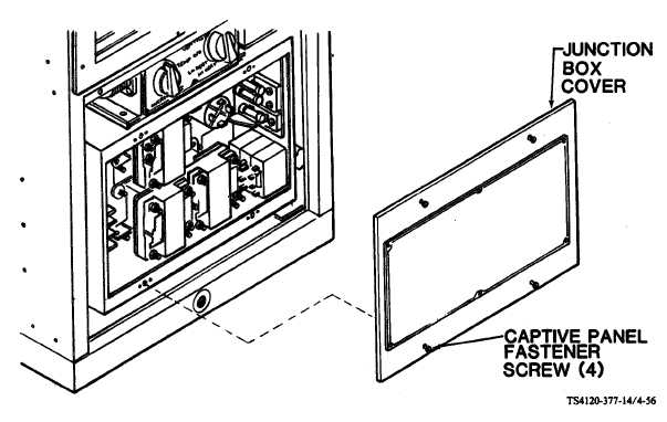
(5) Using screwdriver, loosen four captive panel fastener screws in junction box cover. (6)  Remove  junction Reassemble Figure 4-56. Junction  Box  Cover box cover. (1) (2) (3) (4) (5) (6) (7) Place  junction  box  cover  on  box  and  aline  hardware. Using  screwdriver,  secure  junction  box  cover  with  four  captive  panel  fastener  screws. Insert  bottom  flange  of  lower  front  panel  inside  the  lip  of  the  cabinet  base. Push  top  of  lower  front  panel  into  position. Using  screwdriver,  secure  lower  front  panel  with  two  captive  panel  fastener  screws. Connect  power  cable. Turn  on  power  at  power  source. 4-95

Privacy Statement - Press Release - Copyright Information. - Contact Us - Support Integrated Publishing

Integrated Publishing, Inc. - A (SDVOSB) Service Disabled Veteran Owned Small Business