|
| |
4-51.
TM 5-4120-377-14
b. Test
(1) Connect the probes of a continuity tester or a multimeter set on the lowest OHMS scale to terminal
studs H1 and H2. If the primary winding is open, replace the transformer.
(2) Connect the probes of a continuity tester or a multimeter set on the lowest OHMS scale to terminal
studs X1 and X2. If the secondary winding is open, replace the transformer.
(3) Connect one probe of a multimeter set on high OHMS scale to either terminal stud H1 and H2 and the
other probe to the transformer case. If resistance is less than 500,000 ohms, replace the transformer.
(4) Connect one probe of a multimeter set on high OHMS scale to either terminal stud X1 and X2 and the
other probe to the transformer case. If resistance is less than 500,000 ohms, replace the transformer.
(5) Connect one probe of a multimeter set on high OHMS scale to either terminal stud H1 or H2 and the
other probe to either terminal stud X1 and X2. If resistance is less than 500,000 ohms, replace the transformer.
c. Installation
(1) Position transformer and gasket on outside rear of junction box.
(2) Using wrench, secure transformer with four nuts and lock washers.
(3) See tags and wiring diagram (fig. 4-20) and connect leads.
Follow-on procedure: Install junction box cover and lower front panel. (see para 4-47.)
Preliminary procedure: Remove junction box. (See para 4-46.)
a. Access
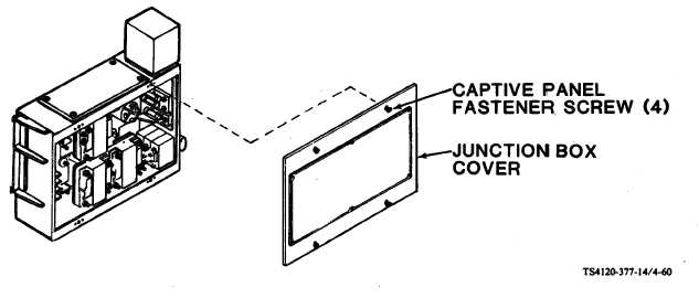
(1) Using screwdriver, loosen four captive panel fastener screws in junction box cover.
Figure 4-60. Junction Box Cover
(2) Remove junction box cover.
4-99
|