|
| |
4-52.
TM5-4120-377-14
NOTE
See paragraph 4-48 for repairs on circuit breaker push-pull reset parts.
e. Installation
(1) Using pliers, pull shaft that holds reset toggles together on circuit breaker.
(2) Place actuator arm into position and reinsert reset toggle shaft.
(3) Using screwdriver, install circuit breaker and circuit breaker cover with six screws, lock washers, and
flat washers.
(4)
(5)
long.
(6)
(7)
(8)
(9)
(10)
Using tags and wiring diagram (fig. 4-20) connect leads with spade type terminals.
For two solder connection leads, cut heat shrink tubing to approximately three-quarter inch (1.9 cm)
Slip heat shrinkable tubing over leads.
Solder leads in place using tags and wiring diagram. (See fig. 4-20.)
Slip heat shrinkable tubing over solder connection and shrink in place.
Remove tags.
Using screwdriver, install junction box cover and tighten four captive panel fastener screws.
Follow-on procedure: Install junction box. (See para 4-46.)
Preliminary procedure: Remove junction box cover. (See para 4-47.)
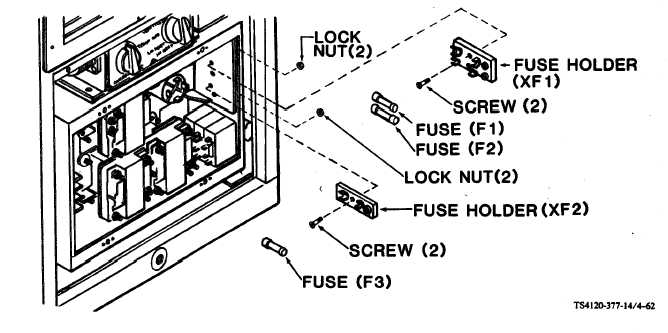
Figure 4-62. Fuses (F1, F2, and F3)
4-101
|