Order this information in Print

Order this information on CD-ROM

Download in PDF Format


Click here to make tpub.com your Home Page

Page Title: LOCATION AND DESCRIPTION OF MAJOR COMPONENTS
Back | Up | Next

Click here for a printable version

Google


Web
www.tpub.com

Home


Information Categories
.... Administration
Advancement
Aerographer
Automotive
Aviation
Combat
Construction
Diving
Draftsman
Engineering
Electronics
Food and Cooking
Math
Medical
Music
Nuclear Fundamentals
Photography
Religion
USMC
   
Products
  Educational CD-ROM's
Printed Manuals
Downloadable Books


TM   5-4120-377-14 
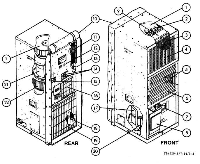
1-8. LOCATION AND DESCRIPTION OF MAJOR COMPONENTS Figure 1-2. Location of Major Components CONDITIONED AIR (EVAPORATOR) FAN -Draws  air  into  the  evaporator  section  and  exhausts  it through the evaporator (cooling) coil and heater elements into the room or enclosure. HEATER ELEMENTS (HR 1 through HR 6) - Consists of two banks of three elements each. Only one bank operates in the LO HEAT mode. Both banks operate in the H1 HEAT mode, however, the temperature control thermostat controls only one bank. MIST  ELIMINATOR  -  Prevents  condensate  (water)  from  being  blown  from  the  coil  into  the  room  or enclosure. CONDITIONED  AIR  DISCHARGE  GRILLE  - Adjustable  louvers  allow  directional  control  of conditioned  air. 1-3

Privacy Statement - Press Release - Copyright Information. - Contact Us - Support Integrated Publishing

Integrated Publishing, Inc. - A (SDVOSB) Service Disabled Veteran Owned Small Business