Order this information in Print

Order this information on CD-ROM

Download in PDF Format


Click here to make tpub.com your Home Page

Page Title: EXPANSION VALVE
Back | Up | Next

Click here for a printable version

Google


Web
www.tpub.com

Home


Information Categories
.... Administration
Advancement
Aerographer
Automotive
Aviation
Combat
Construction
Diving
Draftsman
Engineering
Electronics
Food and Cooking
Math
Medical
Music
Nuclear Fundamentals
Photography
Religion
USMC
   
Products
  Educational CD-ROM's
Printed Manuals
Downloadable Books


TM5-4120-377-14 c.   Installation (1) (2) (3) (4) (5) NOTE Do  not  disassemble  liquid  sight  indicator. Position  liquid  sight  indicator  on  tubing. While  purging  the  system  with  nitrogen,  braze  the  tubing  joints.  (See  para  5-7  and  5-8.) Replace the dehydrator. (See para 5-13.) Leak  test  all  newly  connected  joints  and  those  in  the  repair  area.  (See  para  5-9.) Evacuate  and  charge  the  refrigerant  system.  (See  para  5-10  and  5-11.) Follow-on  procedure:  Install  rear  panel.  (See  para  4-32.) 
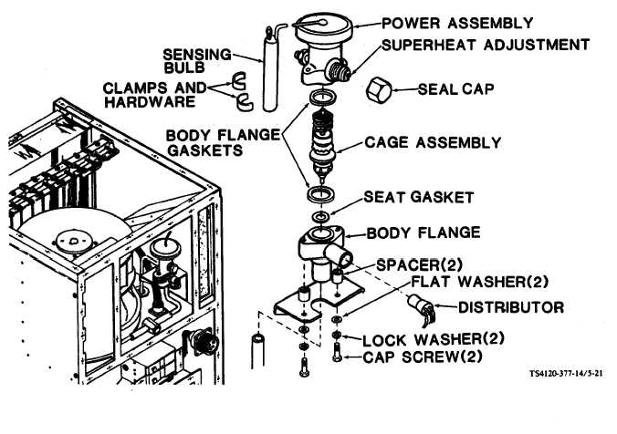
5-22.  EXPANSION  VALVE Preliminary  procedure:  Remove  rear  panel.  (See  para  4-32.) Figure   5-21.   Expansion   Valve 5-43

Privacy Statement - Press Release - Copyright Information. - Contact Us - Support Integrated Publishing

Integrated Publishing, Inc. - A (SDVOSB) Service Disabled Veteran Owned Small Business