|
| |
TM 5-4120-377-14
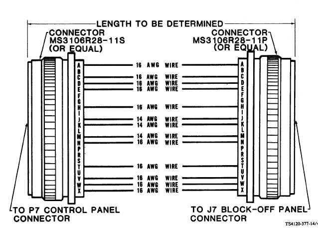
y. Fabricate an interconnecting cable/harness of the required length to connect the P7 block off mounted
connector and the J7 control panel connector.
Figure 4-8. Interconnecting Remote Control Cable Diagram
z. Install interconnecting cable between block off assembly bulkhead connector and control panel
receptacle (J7).
4-8. CABLE CONNECTIONS THROUGH RETURN (CONDITIONED AIR INTAKE) DUCT
This paragraph is applicable only when the conditioned air intake grille and filter (filter relocated in facility
duct work) are to be removed from the unit and one or both of the alternate (input power or remote control
connector) cable locations are to be used. These alternate cable connection locations permit cables to be
routed through the return air ducting to the air conditioner.
Be sure input power is disconnected before doing any work inside air conditioner cabinet.
Voltages used can be lethal.
4-15
|