Order this information in Print

Order this information on CD-ROM

Download in PDF Format


Click here to make tpub.com your Home Page

Page Title: Figure 4-44. Switch Position and Terminal Location
Back | Up | Next

Click here for a printable version

Google


Web
www.tpub.com

Home


Information Categories
.... Administration
Advancement
Aerographer
Automotive
Aviation
Combat
Construction
Diving
Draftsman
Engineering
Electronics
Food and Cooking
Math
Medical
Music
Nuclear Fundamentals
Photography
Religion
USMC
   
Products
  Educational CD-ROM's
Printed Manuals
Downloadable Books


TM5-4120-387-14 (4) (5) c. Test (1) continuity be Indicated. Check between Check switch for evidence  of  overheating  or other visible damage. Replace switch if damaged. 
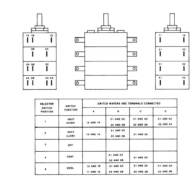
Using multimeter and switch position chart shown on figure 4-46, check at contacts indicated. With  switch  position  closed,  continuity  should With switch position open,    no continuity should be indicated. each set of contacts and at each switch position. Figure 4-44. Switch Position and Terminal Location 4-113

Privacy Statement - Press Release - Copyright Information. - Contact Us - Support Integrated Publishing

Integrated Publishing, Inc. - A (SDVOSB) Service Disabled Veteran Owned Small Business