 |
|||
|
|
|||
|
Page Title:
INSPECTION, TESTING, REPAIR, AND REPLACEMENT |
|
||
| ||||||||||
|
|
 TM 5-4120-393-14
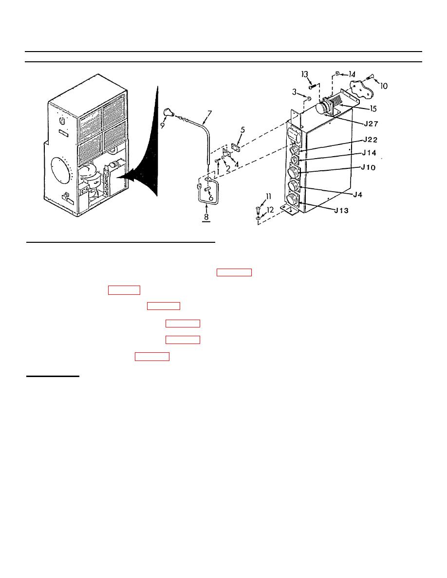
4-40. Junction Box Number One (cont)
INSPECTION, TESTING, REPAIR, AND REPLACEMENT
See the following paragraphs for individual component inspection, testing, repair, and replacement.
1.
Junction Box Number One Harnesses and Leads. See para 4-41.
2.
Circuit Breaker. See para 4-42.
3.
Heater Relays (K1 and K2). See para 4-43.
4.
Condenser Fan Motor Relay (K7). See para 4-43.
5.
Evaporator Fan Motor Relay (K8). See para 4-43.
6.
Compressor Relay (K9). See para 4-44.
INSTALLATION
1.
Using screwdriver and wrench install connector J27 and harness (15) to angle mount on top of junction box with four
each screws (13) and nuts (14).
2.
Place junction box in air conditioner and align mounting holes.
3.
Using screwdriver, secure junction box with two screws (11) and flat washers (12) in lower junction box mounting foot
and three screws (10) in the side of the junction box.
4.
Check that circuit breaker reset knob (9) on rear of air conditioner is pushed in all the way.
5.
Insert push-pull control (7) wire end through hole in top of actuator arm (8).
6.
Flip circuit breaker to OFF (down) position.
7.
Slip core end fitting (6) on push-pull control (7) wire end and use screwdriver to tighten screw.
4-96
|
|
Privacy Statement - Press Release - Copyright Information. - Contact Us |
|
|
Integrated Publishing, Inc. - A (SDVOSB) Service Disabled Veteran Owned Small Business
|

