 |
|||
|
|
|||
|
|
|||
| ||||||||||
|
|
 TM 5-4130-234-13&P
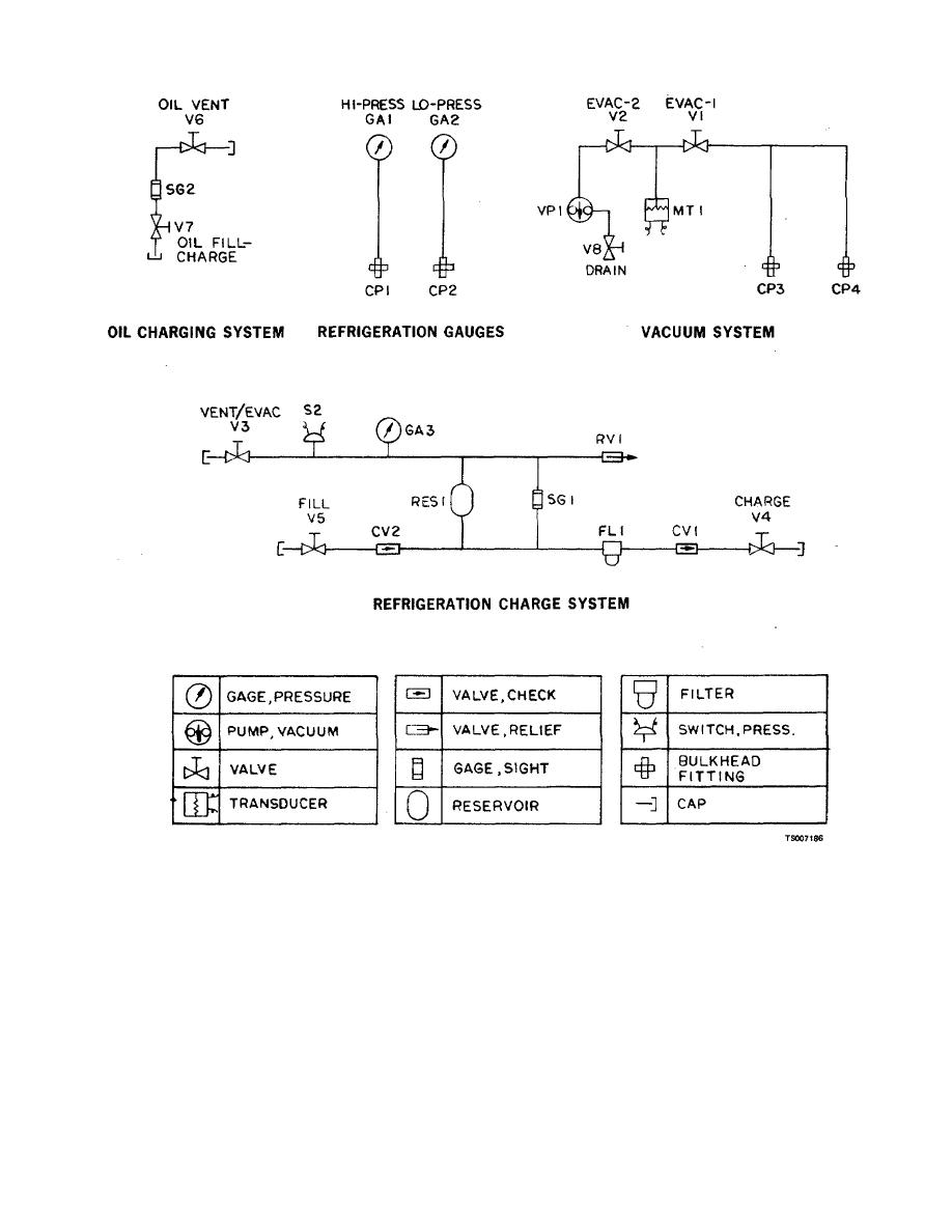
Figure 2-2. Fluid Schematic
b. Filling the Service Unit Reservoir: The service unit
the reservoir is full, all valves are closed, hoses
fluid system is first vented to atmosphere to relieve any
disconnected, and fittings capped.
pressure buildup from any refrigerant left in the fluid
c. Leakage Checking Refrigeration System: The
system. The fluid system is then evacuated to check for
refrigeration system is first pressurized to approximately 15
leakage. A bottle of refrigerant is connected to the FILL
psig with nitrogen. The refrigeration system charge valve
connection, the valve on the refrigerant bottle is opened,
is connected to the service unit LOW PRESS gage and the
the FILL valve is opened, and the VENT/EVAC valve is
refrigeration system charge valve is opened. The pressure
carefully controlled to allow the reservoir to fill by venting
indicated on the low pressure gage is monitored for rapid
the pressure buildup in the reservoir to atmosphere. When
decay. If pressure decays rapidly, the leak detector,
furnished with the
2-3
|
|
Privacy Statement - Press Release - Copyright Information. - Contact Us |
