 |
|||
|
|
|||
|
Page Title:
Table 2-1. Functions of Controls, Indicators, and Connections |
|
||
| ||||||||||
|
|
 TM 5-4130-234-13&P
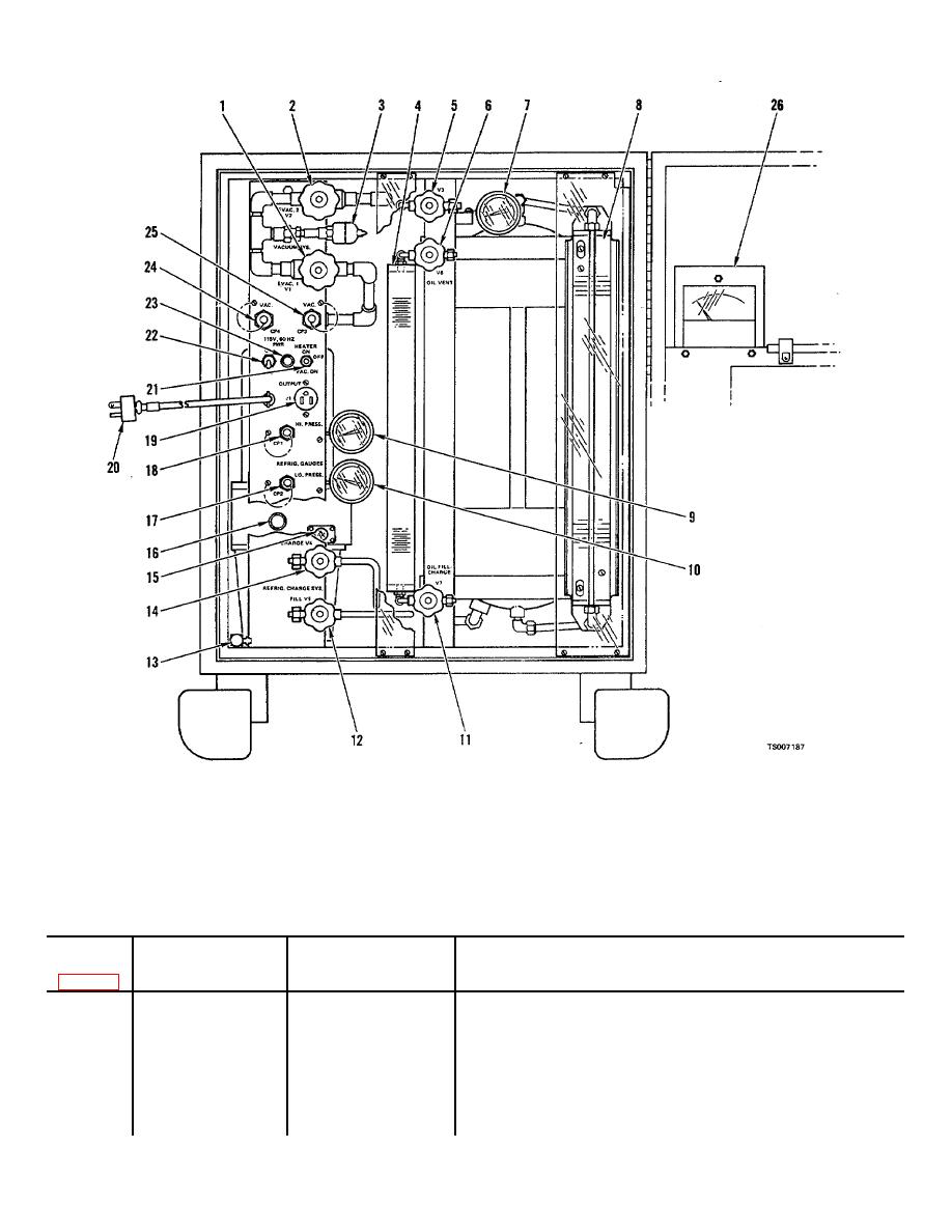
Figure 2-3. Controls, indicators, and connectors
a. Before connecting connector (20) to electrical source, make certain that circuit breaker 122) and switch /21) are
OFF.
b Check vacuum pump oil level at glass disk (15). Oil level must be maintained within sight of glass disk. Oil level
will indicate higher while pump is running.
Table 2-1. Functions of Controls, Indicators, and Connections
Panel Marking
Index No.
and/or Reference
Control, Indicator
Function
Designation
or Connection
1
EVAC 1 V1
Valve
To control vacuum at unions CP3 and CP4.
2
EVAC2 V2
Valve
To control vacuum at vacuum pump.
3
MT1
Thermistor
Combination heater and thermocouple sensing
element to provide signal to gage M1.
4
SG2
Beaker
Scale on beaker displays quantity of refrigeration oil
5
VENT/EVAC V3
Valve
To control ventilation or evacuation of reservoir.
6
OIL VENT V6
Valve
To control vent for refrigeration oil in beaker.
7
GA3
Gage
Measures pressure contained in reservoir.
2-5
|
|
Privacy Statement - Press Release - Copyright Information. - Contact Us |
