 |
|||
|
|
|||
|
|
|||
| ||||||||||
|
|
 TM 5-4130-234-13&P
a. Verify thermocouple gage control for defect and
(5) Close valve (1). Gage (26) must indicate less
inaccuracy before replacement as follow s: (Refer to
than 50 microns.
reference designator M1 and MT1 of fig. 2-1 .1
(6) If gage (26) fails this test, replace entire
(1) Connect service unit to electrical source in
thermocouple gage control (14, figure 5-2) in accordance
accordance with chapter 2, Operating Instruction s.
with section IV.
(2) Connect a certified vacuum gage to union (25,
5-7.
Cable Assembly (1, fig. 5-2).
(3) Open valves (1, 2), set circuit breaker (22) to
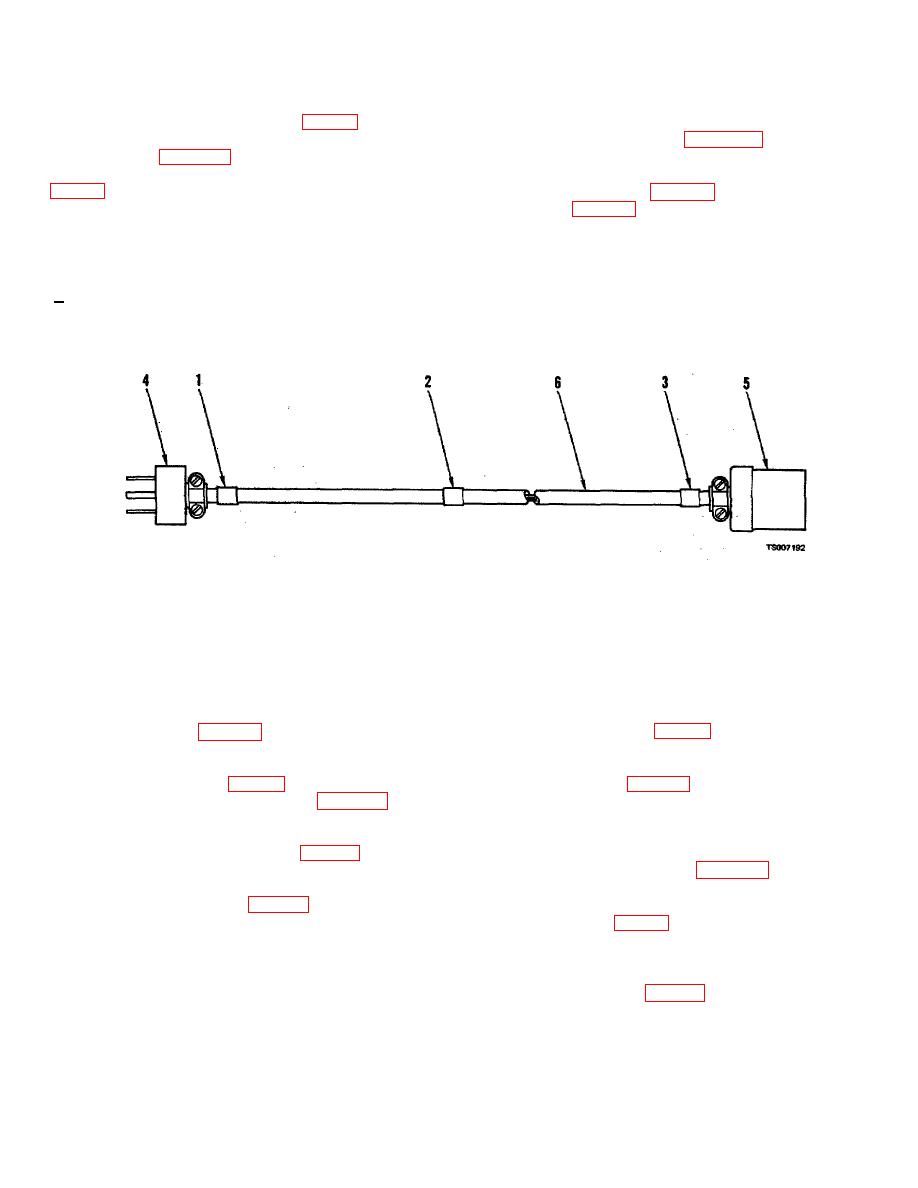
a. If cord (6, fig. 5-3) or connectors (4, 5) required
ON, and set switch (21) to VAC ON.
replacement, strip both ends of wires on cord (6) and
(4) Compare vacuum indication between gage
connect end of black wire to terminal B of each connector.
(26) and certified vacuum gage at 1000, 500, 50, and 20
Connect end of white wire to terminal S of each connector
microns. The minimum accuracy of gage (26) must be 500
and connect end of green wire to terminal G of each
+50 microns.
connector. Secure connectors over outer insulation of cord
(6).
1.
Identification Tie
2.
Identification Tie
3.
Identification Tie
4.
Connector
5.
Connector
6.
Power Cord
Figure 5-3. Power cable assembly
(7) If oil pump (13, fig. 5-2) is defective, replace oil
5-8.
Oil Pump (13, fig. 5-2)
pump.
a. Before replacing oil pump (13), verify pump for
defect as follows:
5-9.
Drain Valve (30, fig. 5-2)
(1) Fill beaker (4, fig. 2-3) with refrigeration oil in
accordance with operating procedure in chapter 2.
a. If drain valve (30) required replacement, hold
(2) Using hose assembly connect suction inlet of
elbow (31) and unthread drain valve.
oil pump to valve (ill.
b. Tape lubricate threads of new: drain valve, hold
(3) Using hose assembly (6, fig. 5-2) with gaskets
elbow (31) and thread new drain valve into fitting to
(3, 4), connect discharge fitting of oil pump to a nitrogen
position drain opening as shown in figure 5-2.
pressurized container of 100 psig.
(4) Open valve (11, fig. 2-3) and hand pump oil
5-10.
Vacuum System Plumbing and Components (8,
from valve (1) into pressurized container. Container
9, 21 thru 57, fig. 5-2)
pressure must not exceed 120 psig. Operate oil pump in a
a. Isolate defective parts by leak checking vacuum
vertical position.
system as follows:
(5) Failure to hand pump 1000 ML of refrigeration
(1) Connect hose assemblies (8, 9) with gaskets
oil into container within five minutes determines a defective
(2, 3) to unions (24, 25, fig. 2-3). Connect other end of
oil pump.
hose assemblies together, using a male union.
(6) Close valve (11). Relieve oil pressure and
(2) Open valves (1, 2), set circuit breaker (22) to
remove hose assemblies.
ON and switch (21) to VAC ON.
(3) Allow vacuum pump to operate for 15
5-8
|
|
Privacy Statement - Press Release - Copyright Information. - Contact Us |
