|
| |
TM 55-8145-221-14&P
Change 1
0002 00-10
REFRIGERATED CONTAINER SYSTEM
EQUIPMENT DESCRIPTION AND DATA – Continued
0002 00
LOCATION AND DESCRIPTION OF MAJOR COMPONENTS - Continued.
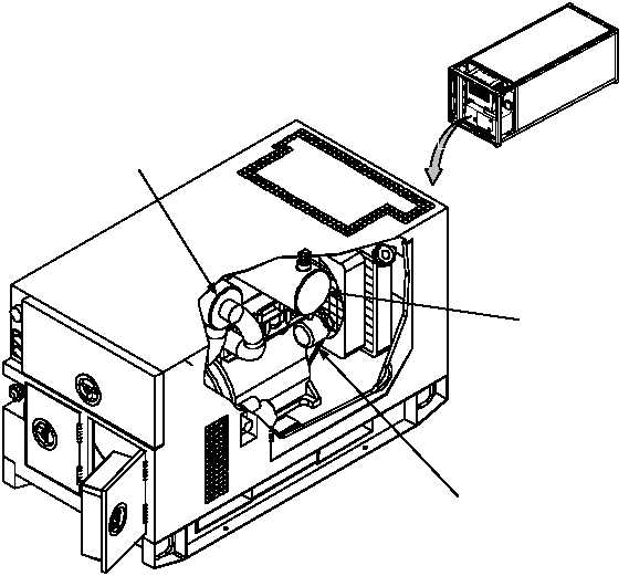
AIR CLEANER ASSEMBLY (1, Figure 7).
The air cleaner assembly is located on the right side behind the engine. It consists of a dry-type, disposable air filter
element made of paper and canister. The air cleaner assembly features a dust collector, which traps large dust particles.
The air cleaner assembly has a restriction indicator that will indicate red when the air filter element requires servicing.
MUFFLER (2).
The muffler and exhaust tubing are connected to the exhaust manifold on the engine. The exhaust exits from the top of
the generator set housing. Gases are exhausted upward.
FAN BELT (3).
The fan belt is located in the engine compartment on the front of the engine. The belt drives the fan, the water pump and
the battery-charging alternator.
1
Figure 7. Generator Set Major Components
3
2
VIEW ROTATED
90 CCW
FOR CLARITY
|