|
| |
TM 55-8145-221-14&P
0002 00-13
Change 1
REFRIGERATED CONTAINER SYSTEM
EQUIPMENT DESCRIPTION AND DATA – Continued
0002 00
LOCATION AND DESCRIPTION OF MAJOR COMPONENTS - Continued.
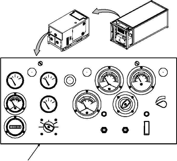
CONTROL PANEL ASSEMBLY (1, Figure 10).
The generator set control panel assembly is located at the rear of the generator set and contains controls and instruments for
operating the engine and the generator.
Figure 10. Generator Set Control Panel
FUEL LEVEL
BATTERY CHARGE
E
F
1/2
FUEL
COOLANT TEMP
OIL PRESSURE
MASTER SWITCH
PRIME & RUN
AUX FUEL
START
OFF
PREHEAT
ENGINE
TOTAL HOURS
EMERGENCY
STOP
PUSH
TO STOP
OFF
OPEN
BATTLE SHORT
VOLTAGE
POWER
ON
OFF
ON
CLOSED
PERCENT
RATED
CURRENT
AC
VOLTS
VIEW ROTATED
90 CCW
1
CONTROL PANEL SHOWN OPEN
HOBBS
QUARTZ
PRIME
& RUN
AC CIRCUIT
INTERRUPTER
PANEL
LIGHTS
PRESS
TO RESET
100
140
180
240
0
80
40
PRESSURE
AMPERS
D.C.
0
-10
+10
+20
CHARGE
DISCHARGE
55
HERTZ
60
65
70
0
25
50
75
100
125
130
60 HERTZ
100
140
180 220
260
300
3
AM-VM
VOLTS
PHASE
L3
3
L3
1
|