|
| |
TM 55-8145-221-14&P
0005 00-7
Change 1
120V
1PH
CB1
FU1
120/
208V
3PH
CAUTION
DISCONNECT LOAD
BEFORE
SWITCHING
120/208V
120/240V
120V
L1,L2,L3,L0
L1,L2,L3
120/
240V
1PH
L3,L0
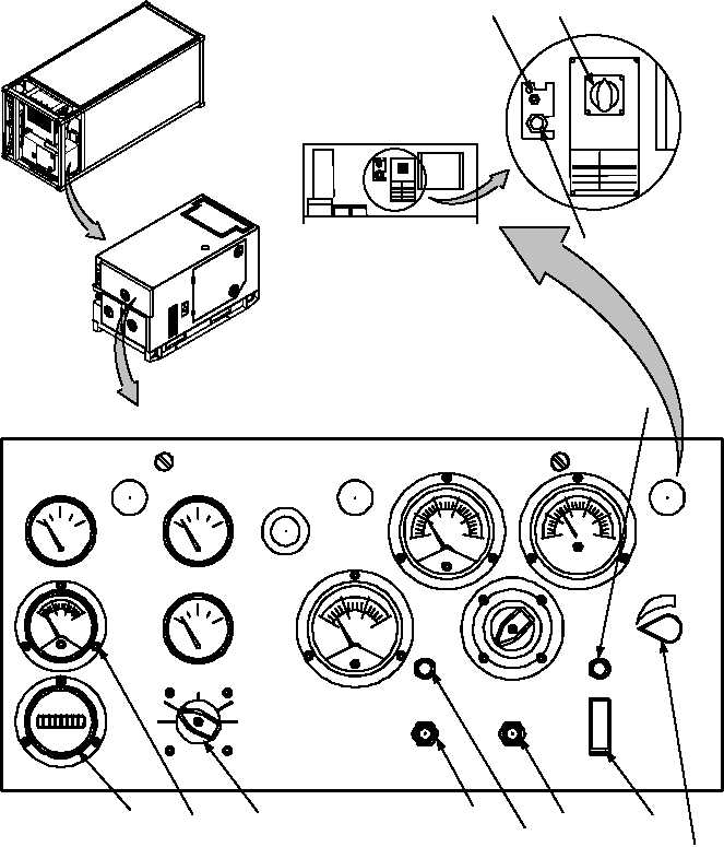
REFRIGERATED CONTAINER SYSTEM
CONTROLS AND INDICATORS – Continued
0005 00
3
VOLTS
PHASE
L3-L1
3
L3-L0
1
PRESS
TO RESET
FUEL LEVEL
BATTERY CHARGE
E
F
1/2
FUEL
COOLANT TEMP
OIL PRESSURE
MASTER SWITCH
PRIME & RUN
AUX FUEL
START
OFF
PREHEAT
ENGINE
TOTAL HOURS
EMERGENCY
STOP
PUSH
TO STOP
OFF
OPEN
BATTLE SHORT
VOLTAGE
POWER
ON
OFF
ON
CLOSED
PERCENT
RATED
CURRENT
AC
VOLTS
CONTROL PANEL SHOWN OPEN
HOBBS
QUARTZ
PRIME
& RUN
AC CIRCUIT
INTERRUPTER
PANEL
LIGHTS
100
140
180
240
0
80
40
PRESSURE
AMPERS
D.C.
0
-10
+10
+20
CHARGE
DISCHARGE
55
HERTZ
60
65
70
0
25
50
75
100
125
133
60 HERTZ
100
140
180
220
260
300
AM-VM
Figure 4. – Control Panel and Indicators (Sheet 2 of 2)
VIEW ROTATED
90 CCW
11
14
13
15
16
17
18
19
LOCATED BEHIND
CONTROL PANEL
20
21
22
12
|