 |
|||
|
|
|||
|
|
|||
| ||||||||||
|
|
 TM 9-4110-241-13
TO 35E9-274-1
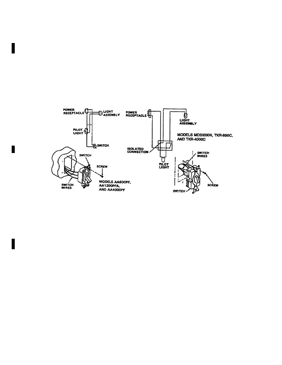
4-20. REMOVE/TEST/INSTALL SWITCH.
a. Tools: (Models AA60OPF, MI 200PFA, and AA4000PF) Screwdriver, cross-tip; (Models MDS1600N, TKR-600C,
and TKR-4000C) Screwdriver, flat-tip.
b. Removal:
WARNING
Disconnect power to power receptacle before beginning this procedure.
(1) Remove two screws and gently pull switch away from wall.
(2) Tag and disconnect switch wires.
Figure 4-15. Switch
c. Test:
(1) Attach leads of multimeter to switch terminals.
NOTE
On Modes MDS1600N, TKR-600C, and TKR-4000C, the two screws on right are
switch screws. The left screw is for isolated connection only.
(2) With switch set to OFF, check for continuity across switch. If there is continuity, switch is defective.
(3) Set switch to ON and check for continuity. There must be continuity or switch is defective.
(4) Set switch to OFF again and verify that continuity is interrupted.
d. Installation:
(1) Connect wires to switch and remove wire tags.
(2) Position switch into wall and secure with screws.
(3) Reconnect power to power receptacle.
4-36 CHANGE 1
|
|
Privacy Statement - Press Release - Copyright Information. - Contact Us |
