|
| |
TM 9-4110-257-14
4-24. CONTROL RELAYS K1, K2 AND K3 TESTING AND REPLACEMENT. - Continued
NOTE
The following procedures apply to all three control relays K1, K2 and K3.
Quantities given are for each relay.
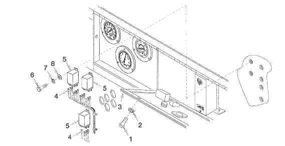
(2) Tag and disconnect wire leads (4).
(3) Remove bolt (6), lock washer (7), flat washer (8), and control relay (5). Discard lock washer.
c.
Installation.
NOTE
The following procedures apply to all three control relays K1, K2 and K3. Quantities given are for each
relay.
(1) Install control relay (5), flat washer (8), new lock washer (7), and bolt (6).
(2) If wire lead (4) terminals were damaged, repair per paragraph 4-20.
(3) Using tags and wiring diagram (fig. 1-4), install wire leads (4). Remove tags.
(4) Close control panel (3). Install two new lock washers (2) and bolts (1).
Figure 4-18. Control Relays
NOTE
FOLLOW-ON MAINTENANCE:
Unlatch and close control panel cover door.
Connect battery (para 4-35) and put unit back into service.
4-62
|