|
| |
TM 9-4120-367-14
TM 07592B-14/1
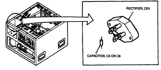
5.4 CAPACITORS C2 (THREE-PHASE UNITS) AND C6 (SINGLE-PHASE UNIT).
Location/Item
Action
Remarks
a. Disconnect power supply.
High voltage can kill.
b. Remove evaporator section top cover.
c.
d.
a.
b.
c.
d.
e.
f.
g.
h.
i.
Figure 5-2. Capacitors C2 (Three-Phase Units) and C6 (Slngle Phase Unit)
Installation
Tag and pull "quick disconnect” terminals from rec-
tifier CR1, terminals 1 and 3.
Cut leads at terminals.
Slip heat-shrink tubing over capacitor leads and
leads X38A20N and X37A20.
Join one capacitor lead and wire X38A20.
Join second capacitor lead and wire X37A20.
Solder "quick disconnect" terminals to the wires.
Heat shrink tubing over the solder joint.
Push terminals onto rectifier CR1, terminals 1 and
3.
Replace junction box.
Replace top cover.
Connect power supply.
Figures FO-1, FO-3, FO-5, or
FO-7.
Use hot air dryer.
Wire X38A20 to terminal 3;
X37A20, to terminal 1.
5-9
Removal
|