Order this information in Print

Order this information on CD-ROM

Download in PDF Format


Click here to make tpub.com your Home Page

Page Title: Figure 5-3. Resistor R1
Back | Up | Next

Click here for a printable version

Google


Web
www.tpub.com

Home


Information Categories
.... Administration
Advancement
Aerographer
Automotive
Aviation
Combat
Construction
Diving
Draftsman
Engineering
Electronics
Food and Cooking
Math
Medical
Music
Nuclear Fundamentals
Photography
Religion
USMC
   
Products
  Educational CD-ROM's
Printed Manuals
Downloadable Books


TM   9-4120-367-14 TM  07592B-14/1 
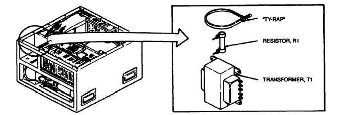
5.5. RESISTOR R1. - Continued Figure 5-3. Resistor R1 Action Remarks Installation a   Slip heat-shrink tubing over resistor Ieads. b.   Use a commercial “butt splice" or solder wire X34A20V (F18H, F18H-3 and F18H-4) or X34A20B (F18H-3A and F18H-4A) to one of the resistor  leads. c.   Solder loose end of resistor to terminal 1 of trans- former T1 . d.   Heat shrink tubing over wire or solder connections. Use hot air dryer. e.   Secure resistor R1 to transform T1 using "Ty- rap." f.   Replace junction box. g.    Replace  top  cover. h.    Conned  power  supply. 5-11 Location/Item

Privacy Statement - Press Release - Copyright Information. - Contact Us - Support Integrated Publishing

Integrated Publishing, Inc. - A (SDVOSB) Service Disabled Veteran Owned Small Business