|
| |
TM 9-4120-367-14
TM 07592B-14/1
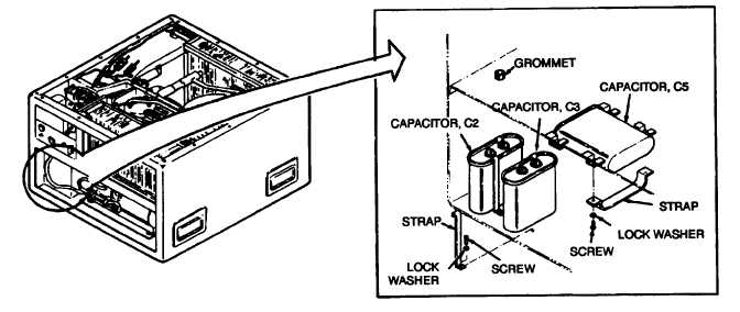
Figure 5-18. Capacitors C2, C3, and C5 (Single Phase)
Location/Item
Action
Remarks
Installation
a. See wiring diagram figure FO-1.
b. Push "quick disconnect" terminals onto capacitor
Capacitor C2
X12A16V
1
X7A16V
2
Capacitor C3
X16B16V
1
X15B16V
2
Capacitor C5
X21A12V
1
X22A12V
2
c. Secure capacitor in place.
d. Replace air filter and louver.
e. Connect power supply.
5.17 CAPACITORS (SINGLE PHASE) C2, C3, C5. - Continued
Wire No.
Terminal No.
Wire No.
Terminal No.
Wire No.
Terminal No.
5-57
terminals.
|