|
| |
TM 9-4120-367-14
TM 07592B-14/1
6.10 COMPRESSOR CRANKCASE HEATER. - Continued
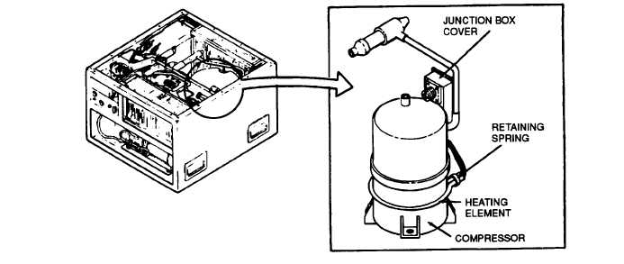
Figure 6-9. Crankcase Heater
Location/Item
Action
Remarks
Removal
f. Spring the ends of the heating element apart
- Continued
slightly so that the heating element can be ma-
neuvered around and over the top of the com-
pressor housing to remove it.
Installation
a. Maneuver the crankcase heating element over
the top of the compressor and down to the lower
part of the compressor housing.
b. Do not spread the ends of the heating element
any more than necessary.
c. Install retaining spring over both ends of the
heating element to hold it in position.
d. Lead electrical wires from heating element into
the compressor junction box.
e. Slide a 1-inch length of heat-shrink tubing over
leads.
f. Solder wire junctions.
g. Use hot air dryer to shrink the tubing.
h. Install cover on junction box.
i.
Connect power supply.
6-37
|