|
| |
ARMY TM 9-4120-381-14
NAVY EE-000-CA-MMA-010/7053-AC
AIR FORCE TO 35E9-136-31
d.
Coat surfaces of metal and gasket with adhesive. Let both surfaces dry until adhesive is tacky but will not stick
to fingers.
e.
Starting with an end, carefully attach gasket to metal surface. Press into firm contact all over.
f.
Install captive fasteners.
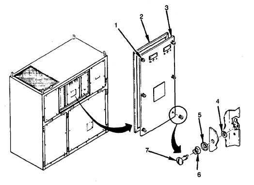
Figure 4-34. Left Electric Plate
2.
Captive Fasteners.
a.
Remove split ring retainer (4), fastener (7), thermoplastic wear washer (5), and ejector spring (6).
b.
Install ejector spring (6), thermoplastic wear washer (5), fastener (7), and install split ring retainer (4).
3.
Electric Plate.
a.
Remove circuit breakers CB1 and CB2 (para 4-62) from damaged plate (3).
b.
Remove electric plate (3).
c.
Install six captive fasteners (1).
d.
Install gasket (2).
e.
Install circuit breakers CB1 and CB2 (para 4-62).
INSTALLATION
1.
Close electric plate (3).
2.
Tighten six captive fasteners (1).
FOLLOW ON PROCEDURE
1.
Install center front evaporator panel (4-22).
2.
Connect air conditioner input power at source.
4-57
|