Order this information in Print

Order this information on CD-ROM

Download in PDF Format


Click here to make tpub.com your Home Page

Page Title: Figure 4-48. Control Box and Components
Back | Up | Next

Click here for a printable version

Google


Web
www.tpub.com

Home


Information Categories
.... Administration
Advancement
Aerographer
Automotive
Aviation
Combat
Construction
Diving
Draftsman
Engineering
Electronics
Food and Cooking
Math
Medical
Music
Nuclear Fundamentals
Photography
Religion
USMC
   
Products
  Educational CD-ROM's
Printed Manuals
Downloadable Books


ARMY TM 9-4120-381-14 NAVY EE-000- CA-MMA-010/7053-AC AIR FORCE TO 35E9-136-31 4-45. CONTROL BOX AND COMPONENTS. -  Continued INSPECTION, TESTING, REPAIR, AND REPLACEMENT - Continued. 2. Left Electric Plate. Circuit breakers CB1 and CB2 (para 4-62). 3.   Right Electric Plate. a. Indicator lights DS1-DS7, DS9 (para 4-48). b. Mode Select Switch SI (para 4-56). c. Knob (para 4-57). d. Service light switch S2 (para 4-58). e. FAULT RESET switch S12 (para 4-59). FOLLOW ON PROCEDURE 1. Close left electric plate (para 4-30). 2. Close right electric plate (para 4-31). 3. 
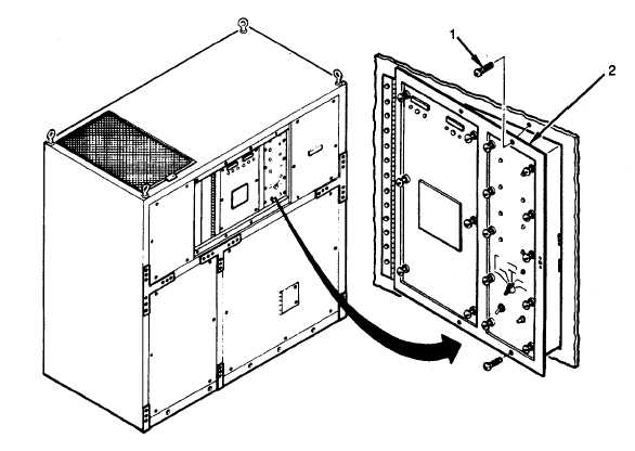
Close control box (2). 4. Install two screws (1). 5. Install center front evaporator panel (para 4-22). 6. Install right front evaporator panel (para 4-25). Figure 4-48.  Control Box and Components 4-84

Privacy Statement - Press Release - Copyright Information. - Contact Us - Support Integrated Publishing

Integrated Publishing, Inc. - A (SDVOSB) Service Disabled Veteran Owned Small Business