|
| |
ARMY TM 9-4120-381-14
NAVY EE-000-CA-MMA-010/7053-AC
AIR FORCE TO 35E9-136-31
1-9.
LOCATION AND DESCRIPTION OF MAJOR COMPONENTS Continued.
c.
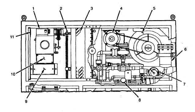
Internal Components Evaporator Section
Figure 1-3. Internal Components Evaporator Section
THERMOSTAT (S9) (1). Senses return air temperature. Controls electric heaters and limits space temperature during
warm up cycle.
ELECTRIC HEATER (EH) (2). Heats supply air.
EVAPORATOR COIL (3). Cools supply air.
EVAPORATOR FAN MOTOR (B1) (4). Drives evaporator fan.
EVAPORATOR FAN (5). Draws mixed return air through evaporator and electric heater. Forces conditioned supply air
through duct work.
DRIER FILTER (6). Used for filtering out refrigerant contaminants in the liquid side of the system.
AIR FLOW SWITCH (S8) (7). Opens if evaporator fan stops and causes EVAPORATOR FAN FAILURE fault light to
come on.
SIGHT GLASS (8). Used for checking refrigerant level in air conditioner.
THERMOSTAT (S14) (9). Senses return air temperature. Controls cooling when operating in return air mode.
TERMINAL BOARD (TB4) (10). Interface for remote operation.
RFI FILTER BOX (11). Input for ac power. Holds fuses F1-F4.
1-4
|