|
| |
ARMY TM 9-4210-381-14
NAVY EE-000-CA-MMA-010/7053-AC
AIR FORCE TO 35E9-136-31
1.
Hinge.
a.
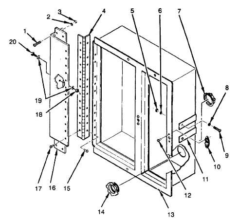
Remove 10 rivets (15) from control box (13).
b.
Remove 13 rivets (17) from frame bracket (16).
c.
Position replacement hinge (4) in mounting position on control box (13).
d.
Install 10 rivets (15) to hinge (4).
e.
Install 13 rivets (17) to frame bracket (16).
2.
Receptacle.
a.
Remove two rivets (12) and receptacle (10).
b.
Install replacement receptacle (10) with two rivets (12).
3.
Bushing and Locking Ring.
a.
Tag and disconnect wiring harness wires (see Figure FO-3).
b.
Remove locking ring (7).
c.
Remove bushing (14).
d.
Install replacement bushing (14) in mounting position.
e.
Install replacement locking ring (7).
f.
Connect wiring harness wires tagged in step 1.
Figure 4-66. Control Box
4-121
|