|
| |
ARMY TM 9-4120-381-14
NAVY EE-000-CA-MMA-010/7053-AC
AIR FORCE TO 35E9-136-31
TESTING
1.
Using multimeter, check continuity between wires 1 and 2, 1 and 3, and 2 and 3. Replace motor if there is no
continuity between any pair of wires. Motor winding is open.
2.
Using multimeter set on high OHMS scale, test stator insulation between each wire (1, 2, and 3) and motor
housing.
A reading of less than 500,000 ohms indicates insulation failure. Replace motor.
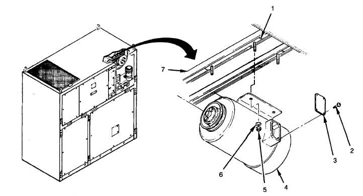
Figure 4-71. Evaporator Motor (B1)
INSTALLATION
1.
Install two brackets (1) loosely with four flat washers (6) and locknuts (5).
2.
Install pulley (para 4-68).
When handling motor, wear gloves to avoid Injury to personnel and to reduce fin
damage on the coil.
3.
Place motor (4) onto slide rails (7) and slide into mounting position.
4.
Reconnect leads and remove tags.
5.
Install J-box cover (3) with four screws (2).
FOLLOW ON PROCEDURES
1.
Install and adjust fan belt (para 4-69).
2.
Connect air conditioner input power at source.
4-135
|