|
| |
ARMY TM 9-4120-381-14
NAVY EE-000-CA-MMA-010/7053-AC
AIR FORCE TO 35E9-136-31
CHAPTER 2
OPERATING INSTRUCTIONS
Section I. DESCRIPTION AND USE OF OPERATOR'S CONTROLS AND INDICATORS
2-1.
GENERAL. The air conditioner is designed for a variety of installations and for operation under a wide range of
climate conditions. Operators must be aware of any peculiarities or operational limitations for their specific installation.
See the appropriate shelter or system manual for instructions peculiar to your specific installation.
2-2.
OPERATOR'S CONTROLS AND INDICATORS. See Figure 2-1 for a general description of the controls and
indicators with which an operator will normally be concerned. For specific operating instructions, see Section III and
Section IV of this chapter.
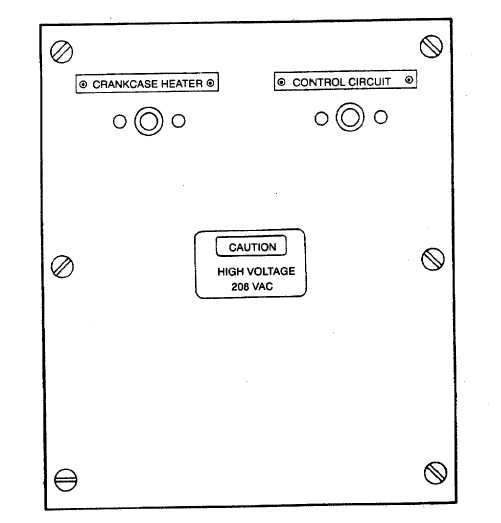
CRANKCASE HEATER (CB1). Provides circuit breaker protection for crankcase heater.
CONTROL CIRCUIT (CB2). Provides circuit breaker protection for the control circuitry.
NOTE
Circuit breakers CB1 and CB2 are located behind the center front evaporator panel.
Figure 2-1. Controls and Indicators (Sheet 1 of 2)
2-1
|