|
| |
ARMY TM 9-4210-381-14
NAVY EE-000-CA-MMA-010/7053-AC
AIR FORCE TO 35E9-136-31
5-46. COMPRESSOR - Continued.
SERVICE - Continued.
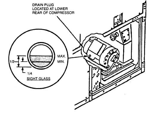
Figure 5-34. Compressor Oil Removal
4.
Adding Compressor Oil (see Figure 5-35).
a. Pump down system (para 5-21).
b. Discharge compressor (para 5-19).
c. Close all manifold valves.
d. Remove yellow 3/8 inch (0.35 cm) hose from hose rack and connect to vacuum pump.
e. Remove yellow 1/4 inch (0.64 cm) hose from hose rack and connect to R-22 refrigerant cylinder positionec for
purging.
f. Open VPV, CGV, and PGV.
g. Start vacuum pump and open ballast valve (on vacuum pump) one turn.
h. Observe gauge reading on vacuum pump for reading of 29-30 Hg.
i. Stop pump and close ballast valve.
j. Close VPV, CGV, and PGV.
k. Remove hose from vacuum pump.
I. Open VPV and CV and purge air out of yellow 3/8 inch (0.35 cm) line.
m. Close VPV and CV and place yellow 3/8 inch (0.35 cm) line in oil container.
5-102
|