|
| |
ARMY TM 9-4120-381-14
NAVY EE-000-CA-MMA-010/7053-AC
AIR FORCE TO 35E9-136-31
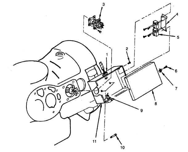
INSTALLATION
1.
Install electrical box (11) with two screws (10) and torque to 16-20 ft-lb.
2.
Install current overload mounting bracket (4) with two screws (2).
3.
Install two bushings (1) and (9).
4.
Pull crankcase heater wire harness through bushing (9) and secure.
5.
Pull wiring harness through wiring harness bushing(1).
6.
Install terminal plate (para 5-51).
7.
Install current overload (para 5-52).
8.
Reconnect leads to terminal plate (3) and current overloads (5), and remove tags.
9.
Install cover (8) with two screws (6) and star washers (7).
10.
Install compressor into air conditioner (para 5-46).
FOLLOW ON PROCEDURE
Connect air conditioner input power at source.
Figure 5-40. Electrical Box Assembly
5-119
|