|
| |
ARMY TM 9-4120-381-14
NAVY EE-000-CA-MMA-010/7053-AC
AIR FORCE TO 35E9-136-31
e.
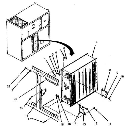
Install line support bracket (34) to coil frame with four screws (36), eight flat washers (29) and (35), and
four locknuts (28).
WARNING
To avoid injury to personnel and/or damage to equipment entire system must be purged with nitrogen
before beginning any brazing operation.
f.
Braze headers (23 and 33 ), and condenser damper actuator line (30) (para 5-14 ).
g.
Install high/low refrigerant switches to condenser coil (para 5-23 and 5-24).
h.
Install low oil pressure switch to condenser coil (para 5-25).
i.
Leak test all newly connected and surrounding area joints (para 5-15).
j.
Evacuate and charge the refrigerant system (para 5-16 and 5-17).
FOLLOW ON PROCEDURE
1.
Install all condenser panels (para 4-27, 4-28, and 6-10).
2.
Connect air conditioner input power at source.
Figure 6-15. Condenser Coil Removal (Sheet 1 of 2)
6-35
|