 |
|||
|
|
|||
|
|
|||
| ||||||||||
|
|
 TM9-4120-423-14&P
2
Soldering Connections. Wire connections must be made mechanically sound before they are
soldered; solder alone does not provide sufficient strength to prevent breakage. Joining surfaces
of connections to be soldered must be clean and bright. If a separate flux is used, it should
conform to Specification O-F-499, Type B, silver brazing flux, and should be brushed onto the
solder. If an uncored solder is used, it should be a lead-tin solder conforming to specification
QQ-S-571 Type SN60WRP2. Wires should always be heated to the point at which the solder
will melt completely and flow into all parts of the joint. Excessive build-up of solder "gobs" on
the joint should be avoided or removed.
3
Securing Wire Bundles. Use lacing tape per MIL-T-43435 to tie wire into bundles.
4
Splicing Wires. To repair broken or cut wires that are otherwise sound, the mating ends can be
stripped and spliced. A commercial butt splice can be crimped onto the ends to join them, or a
"Western Union" wire splice can be made. The latter is made by stripping 1/4 - inch (0.6 - 1.3
cm) of insulation from the wire ends, holding the ends parallel and facing opposite directions,
then twisting each end around the other wire at least three turns. Solder and apply insulation as
described above.
5
Crimping Terminals. To install a terminal on the end of a wire, strip 1/4 - inch (0.6 - 1.3 cm)
of insulation from the end of the wire, insert wire end into the shank of the terminal, and crimp
the shank.
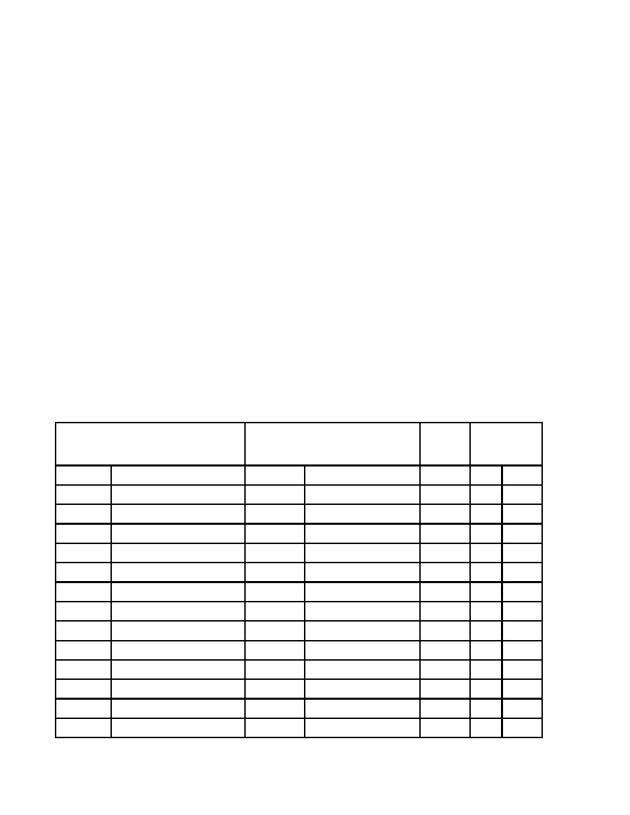
Wire List
TERMINATION
TERMINATION
AWG
LENGTH
WIRE
SIZE
FROM
TERMINAL TYPE
TO
TERMINAL TYPE
IN.
CM.
WIRING HARNESS
P2
P2-A
MS3106R24-11S
TB4-7
MS17143-2
16
41
104.1
P2-B
MS3106R24-11S
TB4-8
MS17143-2
16
41
104.1
P2-C
MS3106R24-11S
TB4-9
MS17143-2
16
41
104.1
P2-D
MS3106R24-11S
TB4-4
MS17143-3
12
39
99.1
P2-E
MS3106R24-11S
TB4-5
MS17143-3
12
39
99.1
P2-F
MS3106R24-11S
TB4-6
MS17143-3
12
39
99.1
P2-G
MS3106R24-11S
E3
MS25036-153
14
44
111.8
P2-H
MS3106R24-11S
TB4-3
MS17143-2
16
39
99.1
WIRING HARNESS
P2A
P2A-A
MS3106R24-11P
J4-D
13207E5347-2
16
35
88.9
P2A-B
MS3106R24-11P
TB1-1
MS25036-153
16
47
119.4
P2A-C
MS3106R24-11P
J4-P
13207E5347-2
16
34
86.4
0015 00-2
|
|
Privacy Statement - Press Release - Copyright Information. - Contact Us |
