 |
|||
|
|
|||
|
|
|||
| ||||||||||
|
|
 TM9-4120-423-14&P
2
Using screwdriver, secure the heater assembly to the flanges of the evaporator coil with four
screws.
3
See tags and wiring diagram and connect heater leads at terminal block TB2. Remove the tags.
4
Install fan and motor assembly (See WP0030).
TESTING
Heater Test (Installed)
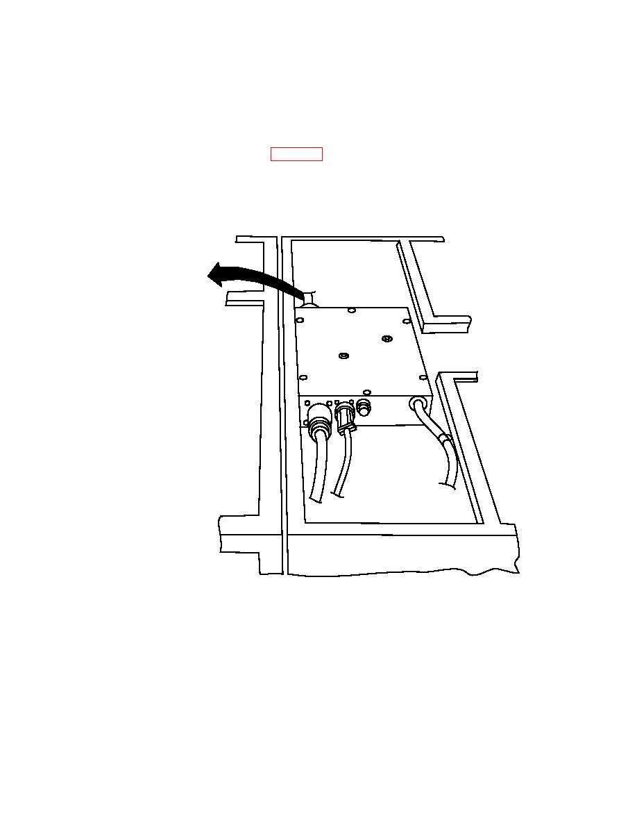
EVAPORATOR SECTION
(TOP COVER REMOVED)
1
Remove heater wiring harness connector P3 from connector J3 on right side of electrical module
assembly.
2
Using multimeter, measure resistance between pins in P3 connector: (Pin G is not used.)
3
A to C, Resistance should be 13 to 19 ohms.
4
A to B, Resistance should be 13 to 19 ohms.
5
B to C, Resistance should be 13 to 19 ohms.
0021 00-4
|
|
Privacy Statement - Press Release - Copyright Information. - Contact Us |
