 |
|||
|
|
|||
|
|
|||
| ||||||||||
|
|
 TM9 4120-423-14&P
INSTALLATION
1
Position rotary switch with locking ring, lockwasher, and nut. Positioning tab on locking ring
must fit into hole in cover.
2
See tags, wire markings, and wiring diagram, and reconnect leads.
3
Remove tags.
4
Align knob setscrew with flat portion of rotary switch shaft.
5
Slip knob onto shaft.
6
Using allen wrench, tighten knob setscrew.
7
Slip box and cover together and align holes.
8
Using screwdriver and wrench, secure box to cover with two screws and self-locking cap nuts.
9
Install remote control assembly in shelter. See WP0057.
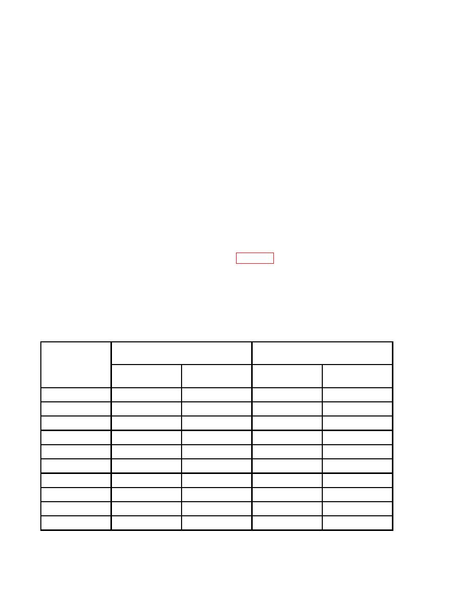
TESTING
The mode selector switch can be tested at the J14 connector located on the back of the remote control
assembly. Using a multimeter, check for resistance values indicated on the following chart.
Resistance Values
Mode
J14 Connector
Resistance Reading (Ohms)
Temperature Control Set To
Pins
Maximum
Maximum
Resistance less
than 2 ohms
WARMER
COOLER
COOL
A to B
C to H
see note
see note
C to N
N to D
N to H
see note
see note
M to P
J to L
1000
1000
J to K
1000
0
K to L
0
1000
OFF
C to N
C to H
see note
see note
N to H
see note
see note
J to L
1000
1000
J to K
1000
0
0059 00-3
|
|
Privacy Statement - Press Release - Copyright Information. - Contact Us |
