 |
|||
|
|
|||
|
|
|||
| ||||||||||
|
|
 TM 9-4120-425-14&P
REMOTE CONTROL MODULE UNIT MAINTENANCE - Continued
0034-00
REMOVAL
Control Module
1.
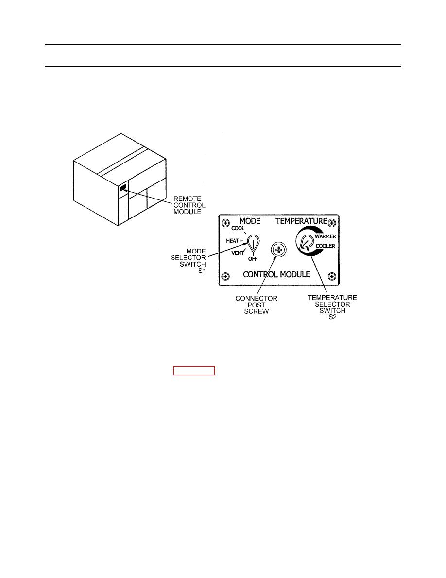
Loosen connector post screw counterclockwise until remote control module is freed from unit. See Figure 1.
Figure 1. Control Module - Front Panel
2.
Carefully pull remote control module straight out of unit to disconnect connector P3 from J3 in rear of remote
control module. See schematic diagram WP 0122-00.
INSPECTION
Temperature Selector Switch S2(15) (Refer to Exploded View Figure 3)
1.
Turn temperature control knob (4) from stop-to-stop to ensure smooth operation. Replace if binding occurs.
2.
Inspect temperature control knob (4) for chips, cracks, or if indicator line cannot be readily seen. Replace if found
defective.
Mode Selector Switch S1(12) (Refer to Exploded View Figure 3)
1.
Inspect selector knob (3) for chips, stripping out, cracks, or damage. Replace if found defective.
2.
Inspect for distinct click when changing positions. Replace switch if not found.
0034-00-2
|
|
Privacy Statement - Press Release - Copyright Information. - Contact Us |
